Viper 5706v install 2005 Silverado ex cab
Printed From: the12volt.com
Forum Name: Car Security and Convenience
Forum Discription: Car Alarms, Keyless Entries, Remote Starters, Immobilizer Bypasses, Sensors, Door Locks, Window Modules, Heated Mirrors, Heated Seats, etc.
URL: https://www.the12volt.com/installbay/forum_posts.asp?tid=138578
Printed Date: April 01, 2026 at 4:18 PM
Topic: Viper 5706v install 2005 Silverado ex cab
Posted By: chevelle212
Subject: Viper 5706v install 2005 Silverado ex cab
Date Posted: March 01, 2015 at 2:29 PM
I've been looking everywhere and cant seem to find much help on installing this alarm/remote start system on my truck. Any help would be greatly aprritiated. It's a 2005 z71 chevy Silverado ex cab
Replies:
Posted By: kreg357
Date Posted: March 01, 2015 at 2:43 PM
This Pictorial on a sister vehicle should help : https://www.the12volt.com/installbay/forum_posts.asp?tid=133000
You will need a bypass module for the Passlock2 immobilizer system. Consider using a full featured bypass module like the Fortin INT-SL+ or the XpressKit DLPKGM module. More bang for the buck as these modules will also handle the door locks, factory alarm, Parking Lights, heated seats and provide a Tach signal & front door trigger's. ------------- Soldering is fun!
Posted By: chevelle212
Date Posted: March 01, 2015 at 3:48 PM
Awesome thank you so much this really helps. What is the passlock2 immobilizer system on my vehicle?
Posted By: kreg357
Date Posted: March 01, 2015 at 4:11 PM
It is a GM designed ignition immobilizer system that prevents the engine from running if the vehicle is not started properly
with a key. It must be bypassed during a remote start as there is no ignition key in the ignition switch at that time. While it
is not the more common "transponder chip" based system used in most newer vehicles, it serves the same purpose.
-------------
Soldering is fun!
Posted By: chevelle212
Date Posted: March 01, 2015 at 4:26 PM
Oh I see. I did notice there is no transponder chip in my key so that makes sense
Posted By: chevelle212
Date Posted: March 01, 2015 at 5:14 PM
Ok so I found both modules online for under 50 dollars. Is one better than the other? Does it hook directly up to the viper remote start module or to the truck itself?
Posted By: kreg357
Date Posted: March 01, 2015 at 6:50 PM
You can download the install guides for the bypass modules to determine which one you prefer.
Here is a link to XpressKit and the DLPKGM :
https://www.xpresskit.com/VehicleCompatibility.aspx?p=&year=2005&make=Chevrolet&model=Silverado&ps=1&s=0&c=0
Here is a link to Fortin INT-SL+ : https://fortin.ca/download/3966/int-sl%2B_installation_guide.rev-20120308.pdf
Both modules are very similar because they are made by Fortin. DEI OEM's the INT-SL+ from Fortin and calls it the DLPKGM.
The install guide provides a wiring diagram and each has a few connections to the vehicle ( +12V, ground and OBD2
J1850 data ).
As for connection between the R/S and bypass module, I almost always go Wire to Wire ( W2W ). It takes a few extra minutes,
but provides excellent reliability. The DLPKGM can do a limited D2D with your Viper system but the INT-SL+ can't. ------------- Soldering is fun!
Posted By: tedmond
Date Posted: March 01, 2015 at 9:55 PM
+1 For Kreg's post. Just adding more info
chevelle212, the bypass will connect to the remote start, and to the car. Think of it as a chain of command. Remote information -> bypass -> car communication protocol.
Either one will work fine for your setup. Using the DLPKGM, it will be ready to go out of the box in DBI (D2D) if you choose, or as Kreg mentioned w2w.
The fortin defaults does not work in d2d unless your remote start is capable of Fortin protocol. In other words, no it will NOT WORK out of the box, However your vendor can FLASH it for Viper D2D.
D2D was a PITA a few years back when it never worked, now they've ironed out the kinks in the ADS(idatalink), DBI(Viper, clifford), COM (compustar) protocols, so I would say go D2D.
Another options is the idatalink ADS-DL or ADS-ALCA. These require a flash for it to work. Very reliable and works a dream. This also needs to be configured for d2d a well.
To sum this in a nutshell, you can use any of the 3 brands mentioned. Xpresskit works right out of the box in data. Fortin works out of the box in w2w only, unless it's programmed for d2d options. Idatalink requires a vehicle specific firmware/changes for it to function, ADS-DL is cheaper than the ALCA.
-------------
Ted
2nd Year Tier 1 Medical School
Still installing as a hobby...pays for groceries
Compustar Expert
Posted By: chevelle212
Date Posted: March 01, 2015 at 11:29 PM
Thank you so much kreg and Ted this info is super helpful. It should make the instalation go smoothly. I just bought the xpresskit xk09. On the website it said that it is an updated module and is compatible with dlpkgm. After I get it I will install it but may need more help as this is my first install. I appritiate the fast response thanks guys
Posted By: tedmond
Date Posted: March 01, 2015 at 11:50 PM
the XK09 requires a specific flash for it to work. Make sure it is flashed with 9.DLPKGM v2.07 or it will not work
-------------
Ted
2nd Year Tier 1 Medical School
Still installing as a hobby...pays for groceries
Compustar Expert
Posted By: chevelle212
Date Posted: March 02, 2015 at 2:06 AM
If when I get this module and it doesn't have the current flash that you are referring to, how would I go about reflashing it?
Posted By: kreg357
Date Posted: March 02, 2015 at 3:27 AM
Looks like they leave the factory with DLPKGM preloaded but... You could ask the seller to verify this or flash it prior to shipment, if that option is still available. You could purchase the XKLoader2 ( online for ~ $30 ) and flash it yourself with the correct firmware or try a friendly BestBuy or local 12V shop.
-------------
Soldering is fun!
Posted By: chevelle212
Date Posted: March 02, 2015 at 1:01 PM
I just verified with the seller that the module does have dlpkgm loaded onto it and it's the current version. Should be here in a few days. I know I'll have more questions on how to hook it up lol
Posted By: chevelle212
Date Posted: March 02, 2015 at 9:20 PM
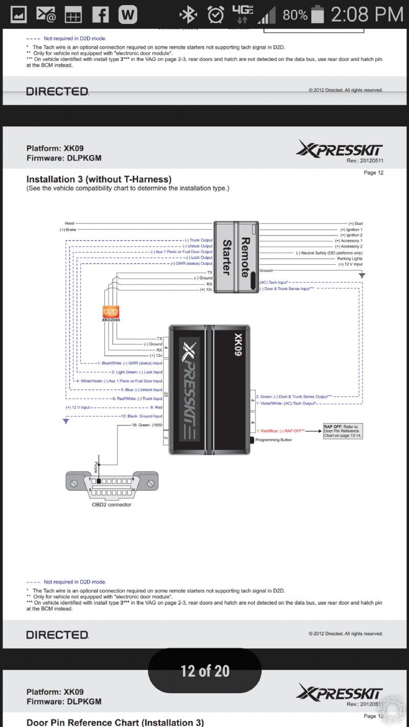
I just uploaded a diagram of the xpresskit xk09. Tell me if I'm reading it correctely. I think it is saying that if you have the d2d plug going from the remote start module to the xpresskit module that the hashed blue line connections on the diagram are not necessary to hook up?
Posted By: kreg357
Date Posted: March 03, 2015 at 4:33 AM
Yes. On the XK09 w/DLPKGM, connect the D2D harness, the J1850 Data wire to the ODB2 connector and possibly the RAP shutdown wire..
-------------
Soldering is fun!
Posted By: chevelle212
Date Posted: March 04, 2015 at 5:27 PM
I have some technical questions about the remote start system. There are a few connections that I am clueless about, even looking at the pictorial. Not sure where these connections go or if they are needed. I tried uploading pics but can't figure out how
Posted By: chevelle212
Date Posted: March 04, 2015 at 5:44 PM
Posted By: chevelle212
Date Posted: March 04, 2015 at 5:45 PM
Posted By: chevelle212
Date Posted: March 04, 2015 at 5:46 PM
Ok so my question is..... what needs to be hooked up to my truck from the remote start and the xk09 module??
Posted By: chevelle212
Date Posted: March 04, 2015 at 6:02 PM
or more specifically the connections that have a 200 mA output or input. Do they all need to be hooked up? And if so do they need their own relays?
Posted By: kreg357
Date Posted: March 04, 2015 at 8:36 PM
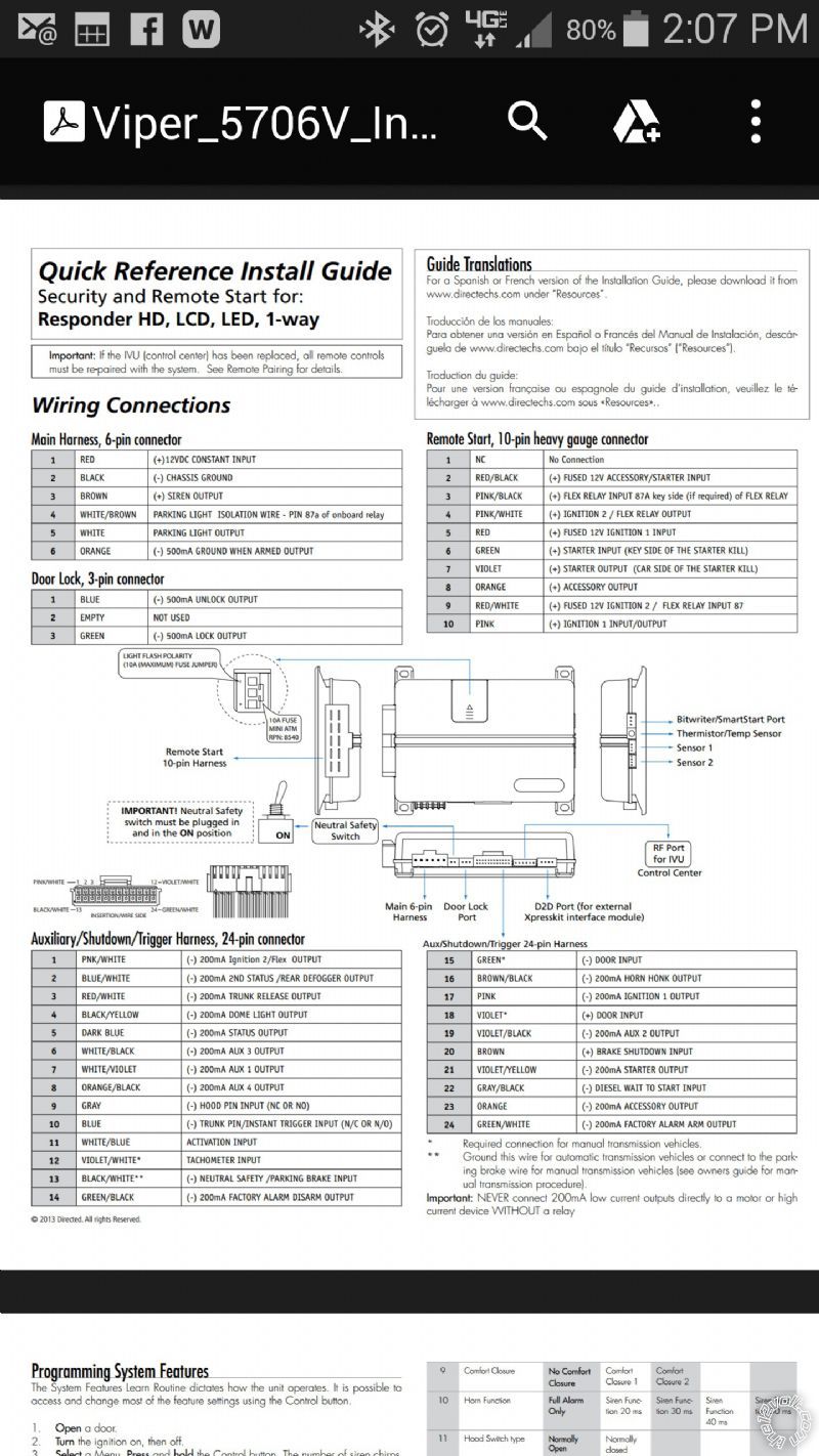
Viper 5706
Main Harness, 6-pin connector
1 RED (+)12VDC CONSTANT INPUT +12V Constant
2 BLACK (-) CHASSIS GROUND Chassis Ground
3 BROWN (+) SIREN OUTPUT Siren
4 WHITE/ BROWN PARKING LIGHT ISOLATION Not Used
5 WHITE PARKING LIGHT OUTPUT *Set to (-) Gray/Black @ BCM Brown Plug
6 ORANGE (-) 500mA GROUND WHEN ARMED Not Used
Door Lock, 3-pin connector
1 BLUE (-) 500mA UNLOCK OUTPUT Handled by D2D
2 EMPTY NOT USED
3 GREEN (-) 500mA LOCK OUTPUT Handled by D2D
Remote Start, 10-pin heavy gauge connector
1 NC No Connection
2 RED / BLACK (+) FUSED 12V ACC/STARTER INPUT thick Red @ ignition switch harness
3 PINK/BLACK (+) FLEX RELAY INPUT 87A Not used
4 PINK/WHITE (+) IGNITION 2 / FLEX RELAY OUTPUT thick White @ ignition switch harness
5 RED (+) FUSED 12V IGNITION 1 INPUT thick RED / White @ ignition switch harness
6 GREEN (+) STARTER INPUT (KEY SIDE) thick Yellow @ ignition switch harness
7 VIOLET (+) STARTER OUTPUT (CAR SIDE) thick Yellow @ ignition switch harness
8 ORANGE (+) ACCESSORY OUTPUT thick Orange @ ignition switch harness
9 RED / WHITE (+) FUSED 12V IGNITION 2 / Flex thick Red @ ignition switch harness
10 PINK (+) IGNITION 1 INPUT/OUTPUT thick Pink @ ignition switch harness
Auxiliary/Shutdown/Trigger Harness, 24-pin connector
1 PNK/WHITE (-) 200mA Ignition 2/Flex OUTPUT Not Used
2 BLUE/WHITE (-) 200mA 2ND STATUS /REAR DEFOG OUTPUT Not Used
3 RED / WHITE (-) 200mA TRUNK RELEASE OUTPUT Not Used
4 BLACK / YELLOW (-) 200mA DOME LIGHT OUTPUT Not Used
5 DARK BLUE (-) 200mA STATUS OUTPUT Handled by D2D
6 WHITE/ BLACK (-) 200mA AUX 3 OUTPUT Not Used
7 WHITE/ VIOLET (-) 200mA AUX 1 OUTPUT Not Used
8 ORANGE / BLACK (-) 200mA AUX 4 OUTPUT Not Used
9 GRAY (-) HOOD PIN INPUT (NC OR NO) To kit supplied hood pin
10 BLUE (-) TRUNK PIN/INSTANT TRIGGER (N/C OR N/O) Not Used
11 WHITE/ BLUE ACTIVATION INPUT Not Used
12 VIOLET/WHITE* TACHOMETER INPUT Handled by D2D
13 BLACK/ WHITE** (-) NEUTRAL SAFETY /PARKING BRAKE IN Chassis Ground ( auto trans only )
14 GREEN/ BLACK (-) 200mA FACTORY ALARM DISARM OUT Not Used
15 GREEN* (-) DOOR INPUT Handled by D2D
16 BROWN / BLACK (-) 200mA HORN HONK OUTPUT Black @ BCM Gray Plug
17 PINK (-) 200mA IGNITION 1 OUTPUT Not Used
18 VIOLET* (+) DOOR INPUT Not Used
19 VIOLET/BLACK (-) 200mA AUX 2 OUTPUT Not Used
20 BROWN (+) BRAKE SHUTDOWN INPUT White @ Brake Pedal
21 VIOLET / YELLOW (-) 200mA STARTER OUTPUT Not Used
22 GRAY/BLACK (-) DIESEL WAIT TO START INPUT Not Used
23 ORANGE (-) 200mA ACCESSORY OUTPUT To extra Relay Pin 85
24 GREEN / WHITE (-) 200mA FACTORY ALARM ARM OUTPUT Not Used
Extra 30/40 Amp SPDT relay with harness
Relay Pin 85 to Viper 23 ORANGE (-) 200mA ACCESSORY OUTPUT
Relay Pin 86 and 87 to thick RED / White @ ignition switch harness through 20 Amp fuse
Relay Pin 30 to Silverado thick Brown ACC2 wire @ ignition switch harness
Plus a 1N4004 diode across Pins 85 to 86 with band towards Pin 86 ------------- Soldering is fun!
Posted By: chevelle212
Date Posted: March 04, 2015 at 11:08 PM
Awesome!! sorry to ask so many questions but I usually do all of my own work on my vehicles and this is something I want to learn. thanks for the help
Posted By: kreg357
Date Posted: March 05, 2015 at 7:25 AM
This is a great opportunity for you. So far you have been "spoon-feed" with the Pictorial for the wires, info about the bypass
modules and the complete Viper wiring chart. Asking questions is fine as long as you have spent the time doing the research
to find the answers and learn first.
You have selected a top of the line, sophisticated R/S system to install. You have a nice truck and will probably keep it for many
years to come. You don't want to take short cuts with this install. You can cause a bit of damage by improper testing and making
incorrect wire connections. While the forum can assist you, in the end, it will be you doing the physical work. You will be locating,
testing and verifying each of the wires. You will be using a Digital Multi Meter to perform this important task. You will be using a
soldering iron / gun to make your connections. These are important skills that, if you don't already have, will be useful throughout
your life.
Here is some more info that will come in handy :
Older Viper 5901 Install Guide : https://www.the12volt.com/installbay/file.asp?ID=741
This guide has more complete descriptions of the wires and the programming options. While some things have changed, the
wire Name and Color usually remains the same along with its' function. The programming options have been updated and
improved but a lot of the basic info remains the same.
Info on diodes can be found on this site : https://www.the12volt.com/diodes/diodes.asp
Info on relays can be found here : https://www.the12volt.com/relays/relays.asp
More detailed relay info can be found here : https://www.bcae1.com/relays.htm
Soldering info / discussions : https://www.the12volt.com/installbay/forum_posts.asp?tid=23856
https://www.the12volt.com/installbay/forum_posts.asp?tid=36483&tpn=1
https://www.the12volt.com/installbay/forum_posts.asp?tid=38022
Here is a link to a recent post that describes the basic DMM set-up and wire testing procedures :
https://www.the12volt.com/installbay/forum_posts.asp?tid=138358 ( About 3/4 the way down on the first page.)
There is a lot to know and a big learning curve. It is not an easy 30 minute job that comes with a step-by-step cookbook guide.
There is a good reason why 12 Volt professional shops charge $600 to do this job. Done right, your truck will provide reliable
service for life. Done wrong and you will be frustrated and disappointed with a rats nest of wires hanging under the dash.
Bottom line, installing this system into your truck can be a very rewarding experience that will have many benefits if you
are willing to spend the time to research, learn and install properly. ------------- Soldering is fun!
Posted By: chevelle212
Date Posted: March 06, 2015 at 11:16 PM
Absolutely. I will defiantly solder all connections. I hate scotch locks and wire taps. They are good for testing to me. They work but I want something that will not fail and will be a sure connection in the future. Thank you so much for the help. I will save a lot of money doing this myself. I already de-pinned all the wires on each harness that I don't need so it will cut down on a lot of unnecessary wires under the dash. I will probably install the system on Monday but I have one more question. Do I need to hook up the RAP OFF connection to my truck? It was a little vague to me.
Posted By: tedmond
Date Posted: March 07, 2015 at 5:33 PM
You should connect the rap shutoff. Although the radio times outs after 30min, its still enough time to run your battery flat. Connect it so it mimics a door opening.
-------------
Ted
2nd Year Tier 1 Medical School
Still installing as a hobby...pays for groceries
Compustar Expert
Posted By: chevelle212
Date Posted: March 09, 2015 at 6:39 PM
Ok I hooked everything up and the doors lock and unlock but the remote start doesn't work.
Posted By: tedmond
Date Posted: March 09, 2015 at 7:21 PM
If your door locks work, your data connection is good. The truck not starting could be multitude of things. Missing ignition wires, viper neutral safety switch not on/plugged in, viper neutral BLACK/ white not grounded.
Any parking light flashes? Shutdown diagnostics? Does it crank?
-------------
Ted
2nd Year Tier 1 Medical School
Still installing as a hobby...pays for groceries
Compustar Expert
Posted By: bs1d3
Date Posted: March 09, 2015 at 7:32 PM
Don't forget to take it out of manual trans mode too!
Posted By: chevelle212
Date Posted: March 09, 2015 at 7:33 PM
Actually just figured it out. When I would try to start it with the remote the running lights would flash 7 times. So I went to the diagnostics section and it said 7 blinks means it's in manual transmission mode. I went into the settings and changed it to auto trans mode and it fired right up. Now it's working great.
Posted By: bs1d3
Date Posted: March 09, 2015 at 7:36 PM
chevelle212 wrote:
Actually just figured it out. When I would try to start it with the remote the running lights would flash 7 times. So I went to the diagnostics section and it said 7 blinks means it's in manual transmission mode. I went into the settings and changed it to auto trans mode and it fired right up. Now it's working great.
Nice!
Posted By: tedmond
Date Posted: March 09, 2015 at 7:43 PM
i forgot to mention manual tranny mode as well. good to know
-------------
Ted
2nd Year Tier 1 Medical School
Still installing as a hobby...pays for groceries
Compustar Expert
Posted By: chevelle212
Date Posted: March 12, 2015 at 10:47 PM
Just want to say thanks to all who helped me with this install. I learned a lot and had a lot of fun with it at the same time. 
Posted By: vital_idol
Date Posted: March 08, 2017 at 8:07 PM
Can someone explain a few things for me regarding this relay? I saw mention of it in a youtube video while doing my pre-install research and then found this posting as well.
Extra 30/40 Amp SPDT relay with harness
Relay Pin 85 to Viper 23 ORANGE (-) 200mA ACCESSORY OUTPUT
Relay Pin 86 and 87 to thick RED / White @ ignition switch harness through 20 Amp fuse
Relay Pin 30 to Silverado thick Brown ACC2 wire @ ignition switch harness
Plus a 1N4004 diode across Pins 85 to 86 with band towards Pin 86
I get the ping 85 and the 200mA accessory wire, the other 3 are confusing me a little. It's the other 3 wires i'm getting confused on. Where are each originating from? In the video I watched, there was no mention of a diode across pins 85 and 86, why is that necessary? i understand diode's make it like a 1 way road, but whats it needed for if each pin already has a connection?
Posted By: vital_idol
Date Posted: March 08, 2017 at 8:09 PM
wow i butchered my sentence structure there. I don't see an edit button either. Repeated myself when referencing the 3 wires.
Posted By: tdbaker021
Date Posted: March 09, 2017 at 12:48 AM
vital_idol wrote:
Can someone explain a few things for me regarding this relay? I saw mention of it in a youtube video while doing my pre-install research and then found this posting as well.
Extra 30/40 Amp SPDT relay with harness
Relay Pin 85 to Viper 23 ORANGE (-) 200mA ACCESSORY OUTPUT
Relay Pin 86 and 87 to thick RED / White @ ignition switch harness through 20 Amp fuse
Relay Pin 30 to Silverado thick Brown ACC2 wire @ ignition switch harness
Plus a 1N4004 diode across Pins 85 to 86 with band towards Pin 86
I get the ping 85 and the 200mA accessory wire, the other 3 are confusing me a little. It's the other 3 wires i'm getting confused on. Where are each originating from? In the video I watched, there was no mention of a diode across pins 85 and 86, why is that necessary? i understand diode's make it like a 1 way road, but whats it needed for if each pin already has a connection?
Relay Pin 85 to Viper 23 ORANGE (-) 200mA ACCESSORY OUTPUT
Connect relay pin 85 to pin 23 ORANGE (-) 200mA ACCESSORY OUTPUT which is located on White 24-pin connector of the viper 5706.
(Orange: (-) ACCESSORY OUTPUT
This (-) 200mA output wire works in conjunction with the Orange wire in the heavy gauge harness. It is
typically used to activate a relay for an additional Accessory wire in the vehicle.)
Relay Pin 86 and 87 to thick RED / White @ ignition switch harness through 20 Amp fuse
Connect pin 86 & 87 to Red or Red/White Constant 12v (Ignition Harness)
Relay Pin 30 to Silverado thick Brown ACC2 wire @ ignition switch harness
Connect Pin 30 to the Brown ACC2 wire (ignition switch harness)
Plus a 1N4004 diode across Pins 85 to 86 with band towards Pin 86
I did not use a diode on my 2006 Silverado.
This is a copy and paste from this forum:
When energizing the coil of a relay, polarity of the coil does not matter unless there is a diode across the coil. If a diode is not present, you may attach positive voltage to either terminal of the coil and negative voltage to the other, otherwise you must connect positive to the side of the coil that the cathode side (side with stripe) of the diode is connected and negative to side of the coil that the anode side of the diode is connected.
Diodes are most often used across the coil to provide a path for current when the current path to the relay is interrupted (i.e. switched off, coil no longer energized). This allows the coil field to collapse without the voltage spike that would otherwise be generated. The diode protects switch or relay contacts and other circuits that may be sensitive to voltage spikes. (JimR, contributor, install bay member)
Posted By: vital_idol
Date Posted: March 09, 2017 at 1:43 PM
Thank you for the response. My plans have changed slightly. I'm now going to be using the FLCAN module instead of the DBALL2.
Not seeing many posts that cover the viper 5706v with the FLCAN in my generation Silverado.
I see on in the pictorials about an 03 Yukon using an idatalink ADS. Is that the same bypass module as the FLCAN, just under a different brand?
Will I run into the same issue of needing to add a relay? If anyone can point me at an existing post that will help, I'd appreciate it.
Posted By: kreg357
Date Posted: March 09, 2017 at 3:09 PM
Yes, the FLCAN is really an ADS AL-CA bypass module that has the DEI DBI D2D comm protocol as it's native,
as shipped, D2D format. As such it will work well with your Viper 5706 system.
In this application with the FLCAN flashed with the DL-GM1 firmware, it will handle the Passlock2 ignition
immobilized system, the Factory Alarm system ( if equipped ), the door locks and provide a Tach signal and
the front doors status all through the D2D connection.
You will still have to connect to the Parking Light, Brake and the rear door status wires.
As for the additional external relay for the trucks ACC2 circuit, that is your choice. Some trucks need
it and others don't.
The Pictorial on the 2003 Yukon should be very accurate for your needs. I believe that the rear door
trigger wires are mentioned later on in the Pictorial.
Also take heed of the Tach signal drop-out warning. Personally, I would connect the Viper directly to
the trucks White Tach wire at the back of the instrument panel. Never an issue that way.
-------------
Soldering is fun!
Posted By: tdbaker021
Date Posted: March 09, 2017 at 10:49 PM
I had to power both accessory wires on my 2006 Silverado. I think the Yukon pictorial even mentions using a relay to power the second accessory wire. I have the Excalibur 2060 with the blade al and it works perfectly wired D2D. Just follow the pictorial and don't overthink the install. It's not bad at all on those trucks.
Posted By: vital_idol
Date Posted: March 10, 2017 at 10:07 AM
sorry if I'm beating a dead horse. starting to get overwhelmed and haven't even started the install.
Regarding this step:
Relay Pin 86 and 87 to thick RED / White @ ignition switch harness through 20 Amp fuse
Connect pin 86 & 87 to Red or Red/White Constant 12v (Ignition Harness)
If I'm understanding correctly, do I need to get a length of wire then for these 2 connections from the relay to splice into the ignition wires? What gauge wire would be appropriate?
Posted By: vital_idol
Date Posted: March 10, 2017 at 11:15 AM
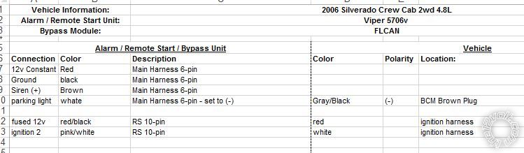
am I filling this out as intended? or does the connection column indicate which harness its on, and description is of which wire?
Posted By: kreg357
Date Posted: March 10, 2017 at 9:56 PM
vital_idol wrote:
sorry if I'm beating a dead horse. starting to get overwhelmed and haven't even started the install.
Regarding this step:
Relay Pin 86 and 87 to thick RED / White @ ignition switch harness through 20 Amp fuse
Connect pin 86 & 87 to Red or Red/White Constant 12v (Ignition Harness)
If I'm understanding correctly, do I need to get a length of wire then for these 2 connections from the relay to splice into the ignition wires? What gauge wire would be appropriate?
The Relay Pin 86 draws very little current. You can connect this wire to the Pin 87 wire right at the relay. Then you would run the Pin 87 wire to it's +12V constant power source. That wire should be fused and needs to be 12 gauge ( 14 gauge would be OK for a short run of less than 15 inches ). ------------- Soldering is fun!
Posted By: vital_idol
Date Posted: March 11, 2017 at 3:40 PM
This thing is killing me and all I'm doing is going over each harness/wire and removing those I won't need. On the previous page that runs through each wire, some say not used and some say handled by D2D. If i'm planning to utilize D2D, then its safe to remove that wire correct?
I'm a little confused on the tach now. I have the wire on the alarm that says its input from Tach, and the wire on the flcan that says output tach. Do those connect? or is that only if i'm not connecting it to the truck tach? As was said in this statement...
"Also take heed of the Tach signal drop-out warning. Personally, I would connect the Viper directly to
the trucks White Tach wire at the back of the instrument panel. Never an issue that way."
If I want to use the truck tach, i connect the viper wire #12 on the harness to it correct? Then I don't need to use the wire on the flcan?
Posted By: vital_idol
Date Posted: March 11, 2017 at 4:42 PM
..... and another question.
Wiring the flcan, i have highlighted the wire in the picture. Does it just splice into an 12v ignition wire? Like the #2 wire from RS harness that I will connect to ignition red wire, can it just be connected at the same splice point? or am i interpreting this wrong?

Posted By: kreg357
Date Posted: March 11, 2017 at 5:52 PM
This is where you really start to get into it.
As for removing the un-used wires : It does keep things neat to de-pin all the un-used wires but if you end up needing them it
could be a PITA. I cut the un-used wires to about 2.5 inches, bundle them into groups by connector and encase them in heat shrink tube. If I end up needing a wire, I can pull it out of the heat shrink and solder the cut section back on. Again, it's your choice.
Here is where it can get confusing. You have decided to go D2D. That means that many signals are handled by the D2D connection.
Lets take the Tach signal. The FLCAN obtains that signal via its' connection to the trucks J1850 wire. It passes that Tach
signal to the Viper via the D2D harness automatically. Supposedly the Viper will use this "Data" Tach signal properly. However,
it is supposed to ignore the Data Tach signal is a Tach signal is hardwired to the Vipers' Violet/White Tach In wire. Interestingly
enough, this Tach In signal could come from the FLCAN's Purple/White Tach output wire or the truck itself at one of several locations.
As previously mentioned, the GM1 firmware has been known to mysteriously drop the Tach Output signal, both Data and hardwire. That
is the reason that I suggested going directly from the Viper to the White Tach wire at the instrument panel. Again, it's your choice.
On this same note about the Tach signal, it is possible to go into the Advanced setting while Flashing the FLCAN module and turn off
the Tach Output.
Yes, the FLCAN Pink IGN (+) In wire gets connected to the Vipers Pink (+) Ign1 output wire which continues to the trucks Pink IGN1
wire.
One thing to remember is that the FLCAN will only supply the front door status to the Viper. If you have a 4 door trunk, you
must add those door trigers to the Vipers' Door Status Input to ensure proper alarm monitoring. This is where you learn about
diodes. Here is the info on the rear door triggers :
Driver's Rear Door Pin LT BLUE/BLACK (-) BCM VIOLET CONN, PIN A3 (ALL MODELS)
Pass Rear Door Pin LT GREEN/BLACK (-) BCM VIOLET CONN, PIN A2 (ALL MODELS)
Diode info can be found on this site. You will need some 1N4001 diodes.
Are we having fun yet?  Now you can see why a good 12V shop charges the amount they do for a quality install. ------------- Soldering is fun!
Posted By: vital_idol
Date Posted: March 12, 2017 at 1:26 PM
This is not going well.... 2 hours in with pretty much zero progress. i've removed the cover, stripped one wire, pinched a finger, stabbed a finger. have fixated on where i'm going to put the alarm brain for way too long.
Any suggestions where it should be put? tried putting it to the right of the metal bracket but not sure that will work.
on verge of breaking down and paying someone but that will just make me upset for much longer...
Posted By: kreg357
Date Posted: March 12, 2017 at 6:15 PM
Don't stress out. I spend some time looking for the best place to locate the R/S unit. Typically it comes down to a secure location that is within wires reach of all the necessary vehicle connection points. Cut the wires to length and route them in groups to their final destination. The closer to a factory appearance, the better. Just be sure to keep away from anything that moves to prevent chaffing and allow extra slack for tilt steering wheels, etc.
-------------
Soldering is fun!
Posted By: vital_idol
Date Posted: March 13, 2017 at 1:23 PM
day 2. have made some progress although haven't touched the RS yet...
Any way of determining the tach wire? like a way to test that its the correct white wire?
Posted By: 07silverado
Date Posted: March 13, 2017 at 2:35 PM
I feel your pain man. ive had my dash torn apart in my daily driver for two days trying to get some help on here and nobody seems to be able to help for some reason and I pretty much have it all done as far as I can tell just having bypass module issues
Posted By: vital_idol
Date Posted: March 13, 2017 at 3:39 PM
oh i've gotten plenty of help. I probably should not have attempted this myself based on how much help i've needed, but on the plus side, I think i'm nearing the finish line.
couple more wires on the RS and the tach wire. Then just need to figure out how the rear doors get wired. so far, its 2 wires on the BCM that I'm guessing i connect 2 of the wires on the Viper that say door input. somewhere in there i need diodes.
Oh then the part i'm afraid won't be to my liking, cleaning it up and putting everything back together and hoping it doesn't look like a hack job.
Posted By: 07silverado
Date Posted: March 13, 2017 at 4:54 PM
that's good people are helping you. I wish I could get the same lol
Posted By: kreg357
Date Posted: March 13, 2017 at 8:47 PM
Here is the rear door pin isolation wiring using two 1N4004 diodes. If you were going W2W, you could add the FLCAN front door trigger output to this and input all three signal to the Vipers (-) Door Trigger input wire.
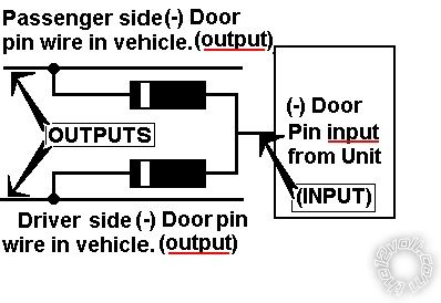 ------------- Soldering is fun!
Posted By: vital_idol
Date Posted: March 14, 2017 at 2:48 PM
so everything is wired up and i tried testing. RS fails and i get 8 flashes on brake lights. I
according to viper doc, it says that means wire 13 isn't grounded. I have double checked that it is.
Any suggestions?
I was getting 7 flashes, found that meant manual transmission mode, followed instructions to set to automatic, now i get the 8 flashes.
Posted By: vital_idol
Date Posted: March 14, 2017 at 2:56 PM
ok i'm dumb. Guess I didn't understand the instructions. I did not attach the neutral safety switch. attached that and it works now.
Can anyone explain what that switch is for?
Posted By: vital_idol
Date Posted: March 14, 2017 at 3:18 PM
so now i'm on the last thing before clean up / completion.
The rear door triggers. I've seen multiple postings that say same thing, about them being on a purple or violet plug at BCM. I don't have a purple plug, or I am looking in the wrong place.
NOTE #5: On BASE Model trucks, the Door Trigger wires are @ the BCM, LT BLUE PLUG, PINS B4 and A5. On 4-Door Trucks the LEFT REAR Door is a LT BLUE/BLACK (-) PIN A3 and the RIGHT REAR Door is a LT GREEN/BLACK (-) PIN A2, located in a PURPLE PLUG at the BCM, use all 4 wires and diode isolate when installing an alarm system.
These notes always say BASE model, if my truck is an LS, would the same wiring apply?
Posted By: vital_idol
Date Posted: March 14, 2017 at 3:19 PM
ok found a note that says purple plug is on the back of BCM. I'll take a look. Thanks everyone!
Posted By: vital_idol
Date Posted: March 14, 2017 at 3:53 PM
found the door wires.
Now it appears my ignorance has no bounds... box says this alarm comes with a status LED. I'm not seeing any type of status LED to install. I'm thinking of the blinking light I use to see in dash boards. Is there supposed to be one? Didn't notice any mention of it in wiring info.
Posted By: vital_idol
Date Posted: March 14, 2017 at 3:54 PM
perhaps its the LED on the control center/antenna?
Posted By: kreg357
Date Posted: March 14, 2017 at 4:32 PM
vital_idol wrote:
perhaps its the LED on the control center/antenna?
Yes, on the antenna.
------------- Soldering is fun!
Posted By: kreg357
Date Posted: March 14, 2017 at 4:35 PM
vital_idol wrote:
ok i'm dumb. Guess I didn't understand the instructions. I did not attach the neutral safety switch. attached that and it works now.
Can anyone explain what that switch is for?
The Neutral Safety switch is another way to disable the remote start function. Think of it as a safety switch for when you are having the truck serviced. The Hood Pin should be enough but it is extra protection. ------------- Soldering is fun!
Posted By: vital_idol
Date Posted: March 14, 2017 at 7:44 PM
all done!!
Thanks for all the help everyone! Kreg357, thank you for the specifics on the door wiring and answers to the relay questions.
Everything appears to work and even was able to make the safety switch non-visible but easily accessible.
No extra screws left after putting dash back together, always a plus.
I would never choose to solder 12 gauge wires to each other again. That was time consuming.
|