Can anyone provide the install diagram for a 2015 Honda Pilot installing a Viper 4606? Im using a Idatalink DBI-ALDL for bypass. Its already programmed to HA3. I can wire it. Its the 4606 im not 100% positive on. Especially the 8 pin Heavy connector. Do i hook yellow to the violet? What others do i need of that connector as well? Also what do i need to wire on other connectors to get it to lock unlock etc and run power liftgate. I cant really find a direct wire diagram for it. I read possibly ill need a couple diodes for unlock function? the DBI ALDL im just going to run D2D and wire it to the green connector. Thank you and greatly appreciate time
-------------
Eric M
PILOT 2009-2016
KEY T-HARNESS IMMOBILIZER
N/A N/A HONDA'S TRANSPONDER ANTI-THEFT SYSTEM, VEHICLES 2015 AND UP REQUIRE A DBALL2 INTERFACE FOR REMOTE STARTING. See NOTE #1
PART COLOR LOCATION DIAGRAM
12 VOLT CONSTANT WHITE (+) @ IGNITION SWITCH, (WHITE, 5-Pin Plug) Pin 2
STARTER YELLOW (+) @ IGNITION SWITCH, (WHITE, 5-Pin Plug) Pin 1
STARTER 2 N/A
IGNITION 1 PINK (+) @ IGNITION SWITCH, (WHITE, 5-Pin Plug) Pin 5
IGNITION 2 N/A
IGNITION 3 N/A
ACCESSORY/HEATER BLOWER 1 ORANGE (+) @ IGNITION SWITCH, (WHITE, 5-Pin Plug) Pin 3
ACCESSORY/HEATER BLOWER 2 RED (+) @ IGNITION SWITCH, (WHITE, 5-Pin Plug) Pin 4
KEYSENSE N/A
PARKING LIGHTS ( - ) GRAY (-) (REQUIRES #775 RELAY) @ HEADLIGHT SWITCH, (BLACK/WHITE, 12-Pin Plug) Pin 11
PARKING LIGHTS ( + ) GRAY (+) @ DASH FUSE BOX, (LT. GREEN, 42-Pin Plug) Pin 19
POWER LOCK PINK (TYPE B), See NOTE #2 @ POWER WINDOW Master Switch, (GRAY, 37-Pin Plug) Pin 28
POWER UNLOCK WHITE (-) and RED (-) TYPE B, (DOUBLE PULSE Required), See NOTE #2 @ POWER WINDOW Master Switch, (GRAY, 37-Pin Plug) Pins 29 and 31
LOCK MOTOR WIRE LIGHT GREEN (5-wire type)
DOOR TRIGGER YELLOW (-) @ DASH FUSE BOX, (LT. GREEN, 42-Pin Plug) Pin 37
DOMELIGHT SUPERVISION PINK (-) Above DRIVERS KICK PANEL, (GRAY, 2-Pin Plug) Pin 1
TRUNK RELEASE ORANGE (-) (Liftgate) NOTE #3 and #4 @ DASH FUSE BOX, (LT. GREEN, 42-Pin Plug) Pin 13
SLIDING POWER DOOR N/A
HORN GRAY (-) @ HORN SWITCH, (WHITE, 20-Pin Plug) Pin 1
TACH Any wire NOT YELLOW/BLACK (AC) @ Any FUEL-INJECTOR
WAIT TO START LIGHT N/A
BRAKE LIGHT BLUE (+) @ BRAKE SWITCH or DASH FUSE BOX, (LT. GREEN, 42-Pin Plug) Pin 34
FACTORY ALARM DISARM DISARMS with UNLOCK
ANTI-THEFT HONDA'S TRANSPONDER ANTI-THEFT SYSTEM, See NOTE #1 @ IGNITION SWITCH TUMBLER
NOTES
NOTE #1: HONDA'S TRANSPONDER SYSTEM, Requires Bypass Module: (For Remote Starting Only) Part #791 Bypass, (Requires Extra Key) for Operation. (For Remote Starting Only) Part # PK-ALL Bypass. (No Extra Key Required for Operation) 2-KEYS Required to Program Module. (For Remote Starting/Door Locks) Part # DBALL2 (No Extra Key Required for Operation) 1-KEY Required for Programming.
NOTE #2: METER THE DOORLOCK WIRES WHILE TURNING THE KEY IN THE DRIVERS DOOR CYLINDER. WHITE IS THE DRIVER DOOR KEY CYLINDER, WHITE IS THE UNLOCK WIRE AND THE RED IS THE DOOR UNLOCK DETECTION WIRE. USE BOTH WIRES AND DIODE ISOLATE EACH.
NOTE #3: THE HATCH GLASS RELEASE WIRE, IS A PINK (-) LOCATED IN THE DRIVERS KICK PANEL, AT A WHITE, 18-PIN PLUG, PIN 8. TEST THESE WIRES WHILE OPENING THE LIFTGATE/HATCH GLASS FROM THE HANDLE ON THE REAR OF THE VEHICLE.
NOTE #4: ON VEHICLES WITH POWER TAILGATE, THE OPEN/CLOSE WIRES ARE BROWN (SWITCH) AND PURPLE to WHITE (COMMON), ABOVE THE DRIVERS KICK PANEL, IN A WHITE,24-PIN PLUG, PINS 20 AND 9. THESE WIRES SHORT WHEN THE SWITCH IS PRESSED.
https://www.the12volt.com/installbay/forum_posts.asp?tid=135857-------------
~wirewise~
Verify all wiring with your meter before making any connections!
Ok THis connector has park light flash wire. Main Harness, White 6-pin connector
1 RED (+)12V DC CONSTANT INPUT
2 BLACK (-) CHASSIS GROUND
3 BROWN (-) 200mA HORN HONK OUTPUT
4 WHITE/BROWN PARKING LIGHT ISOLATION WIRE - #87a NORMALLY CLOSED of onboard relay
5 WHITE PARKING LIGHT OUTPUT- #30 COMMON of onboard relay
6 ORANGE (-) 500 mA (GWA) GROUND WHEN ARMED OUTPUT
so if i set my viper to flash lights + polarity i just need to tie #5 white wire into this wire(PARKING LIGHTS ( + ) GRAY (+) @ DASH FUSE BOX, (LT. GREEN, 42-Pin Plug) Pin 19 ) and not need to relay the - wire?
My door lock connector has 3-pin connector
1 BLUE (-) 500mA UNLOCK OUTPUT
2 EMPTY NOT USED
3 GREEN (-) 500mA LOCK OUTPUT
Do i need one or both of those and if so what ones tie into which unlock and sense wire with diode?
Thank you for fast response. I can figure out the rest with that info.
-------------
Eric M
Awesome. Thanks for the info.
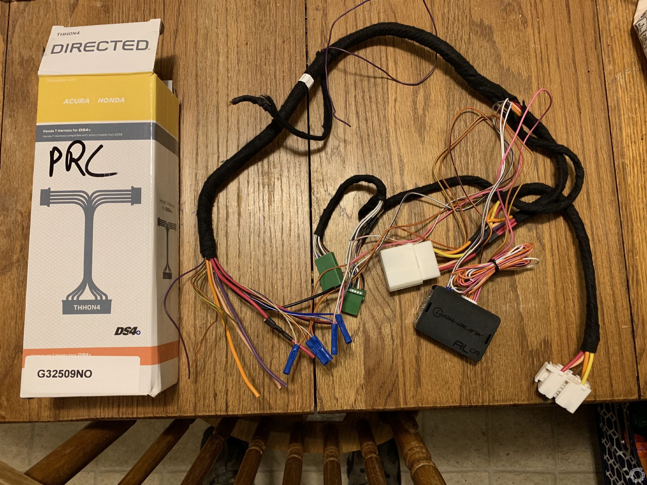
I bought a directed t harness for a DS4+ Setup off eBay for like $15 and cut off the ends that connect to DS 4. Lets me T the ignition and Data connectors so Ill have minimal wires to tap into. Figured for $15 it will save a bunch of wire time as well as make removal easy if I sell vehicle in future.
So far as the power lift gate goes... It looks as the purple and brown wire short when the button is pressed according to the other post I see
On models with power tailgate, the open/close are brown (switch) and purple (com), above the driver kick, white 24 pin plug, pins 20 and 9 or white 16 pin plug, pins 1 and 5. These wires short when the switch is pressed.
For that should I take a - accessory output from viper and use 2 diodes to send a - signal to them both? Or use a relay to short them? The factory fob or switch in door need long pressed to open gate.
Sounds like a simple install. You all are awesome and its greatly appreciated
Thank you.
-------------
Eric M
I think before I got carried away, I would see what the Viper Trunk Release button and the ADS AL-CA do.
While the Pilot in the Pictorial did not have a power liftgate, the R/S system did pop the rear glass
panel when the R/S Trunk Release button was pressed. Going by the DL HA3 install guide, it does call
its' output signal Trunk/Hatch Release and Trunk/Liftgate so it might just handle the power liftgate.
If it does not, you can always add that feature. I would use a mini-relay controlled by either the
Trunk Release output or an AUX output. You would need to verify the proper wires mentioned in that
info you listed. No diodes would be necessary. Relay wiring below :
Relay Pin 86 to +12 Constant
Relay Pin 85 to Viper Trunk Release or AUX output
Relay Pin 30 to either wire, say Brown
Relay Pin 87 to either wire, say Purple
The relay would do the same thing the Pilots Trunk Release switch does. Also check to see if the
power liftgate actuates the alarm. You might have to do a Disarm prior to opening the rear hatch.
The bypass module should do this for you if it opens the liftgate.
-------------
Soldering is fun!
Ok. Makes sense. Sounds easy enough. Yeah this Pilot wont open gate until unlocki/disarm from factory remote. Ill make sure to disarm if I have to relay it which would definitely override that unlock only function if a relay forces the signal.
If I didnt already have the viper Id of just went all idatalink with blade. I also have an Automate 5304a which is pretty much a Viper 5706v far superior to the 4606 but I dont want the alarm function in this install. Ill probably program my 2 way remotes to this viper after everything gets working. Its a LCD remote.
Anyhow thanks again for help. Ill be sure to report on what works with this AL CA.
-------------
Eric M
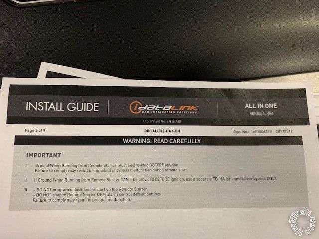
Ok. So i just noticed on page 3 of the idatalink DBI-AL instructions it requires a Ground When Running connection from the Viper.
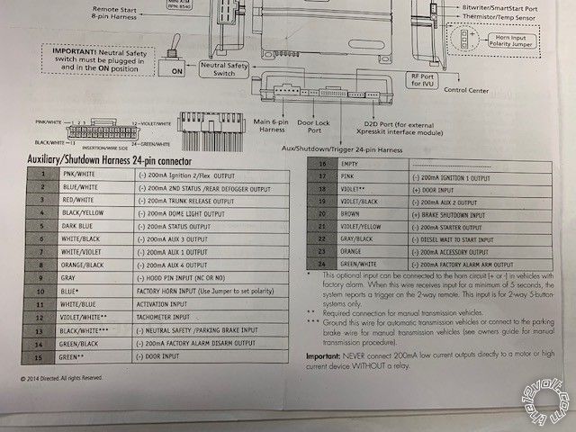
Would this be the dark blue wire (pin 5) on 24 pin connector of viper? And where do i connect this wire?
Thanks
-------------
Eric M
I'll give that a "conditional yes".
Two things to mention :
1. If you are going D2D between the Viper and the ADS AL-CA, GWR to (-) Status Output is handled by the D2D harness. There is no reason to run a hardwire connection. If you are going W2W, then, yes, you must make the physical hardwire connection.
2. That note about the ADS AL-CA GWR input has to do with signal timing and not the connection type. It should not be an issue with a current model Viper system as they have the correct Status output timing.
-------------
Soldering is fun!
So I grounded the black white wire pin 13 and everything works.
It remote cranks and starts. Stays running. The odd issue though is the ADS-AL CA is constantly buzzing/clicking like a relay or something inside it is going off.
This is while its running only. This cant be norm Id guess. Any thoughts?
-------------
Eric M
Strange, I don't remember any unusual noises with the one I did in the Pictorial. Think there was only one vehicle I did where the bypass module made noises and that was an ADS TB on a Ford Explorer.
-------------
Soldering is fun!
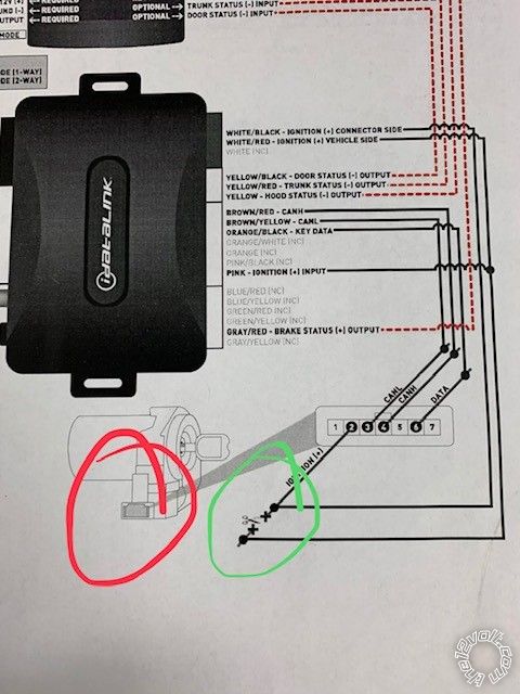
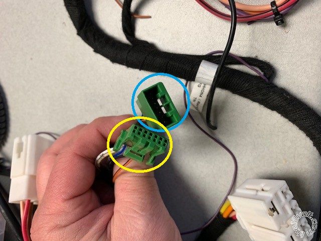
Yeah unless i have the ignition wires flipped. Circled in green in Idatalink pic. I Wasn't 100% positive on "Connector Side" vs "Vehicle Side" as they are labeled on wiring diagram. Vehicle or connector circled in red?. I have a T harness "as pictured" splitting the Ignition and Transponder plugs. I have the White/Black wire running to the wiring harness side "Female Connector circled in blue in pic" and the white/red and pink wires are connected to the "Male Connector circled in yellow" side that plugs into the transponder.. So is the transponder considered "Connector or Vehicle Side" ? I suppose if these were flipped it would still work and maybe cause this issue.
-------------
Eric M
I think i have the two Ign wires flipped after further research. Looks like the W/B wire needs to go to the Female connector side of the T harness. IE the Connector Side
and the W/R and Pink wire to the Male side of my T harness IE the Vehicle side.
My lack of sleep is catching me. Makes more sense after more thought seeing as how the Pink is an input and would need to be connected to the output of the harness. Like say the Vehicles harness supplying the + ign.
It must be making the power relay inside the ADS flutter. Why it works IDK but i'm sure a flip of two wires will make it quiet as a mouse.
Oh well. Another cup of coffee and some heat shrink soldering and i should be good to go.
Thanks all for the input.
-------------
Eric M
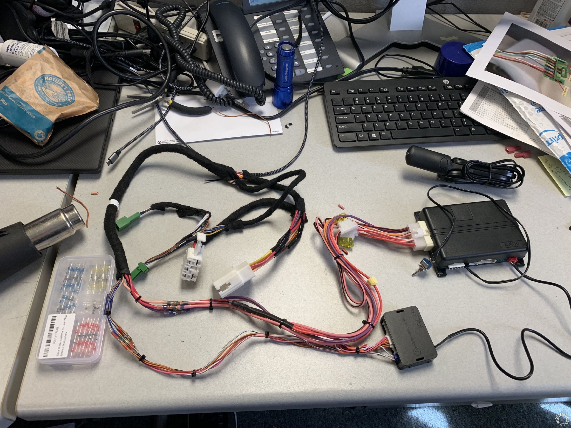
So now all together in correct order with those awesome heat shrink and solder all in one connectors. Using my modified $16 Directed DS4 T harness off eBay I cut the connectors off and wired into. Should make a nice clean install. I think Ill be good to go.
-------------
Eric M
Yeah. Working good now. No buzzing after wire flip. Thanks again for everything l. Greatly appreciate it.
-------------
Eric M