BMW E39 Remote Starter Wiring Confusion
Printed From: the12volt.com
Forum Name: Car Security and Convenience
Forum Discription: Car Alarms, Keyless Entries, Remote Starters, Immobilizer Bypasses, Sensors, Door Locks, Window Modules, Heated Mirrors, Heated Seats, etc.
URL: https://www.the12volt.com/installbay/forum_posts.asp?tid=145719
Printed Date: May 13, 2026 at 4:19 AM
Topic: BMW E39 Remote Starter Wiring Confusion
Posted By: bmwe39528i1998
Subject: BMW E39 Remote Starter Wiring Confusion
Date Posted: October 28, 2019 at 10:16 PM
I've been searching the net for a couple of days on this. The information seems pretty scarce for a 22 year vehicle...
Finally decided to register on this website as people here seem quite knowledgeable.
I was able to install the remote on my BMW 528i 1998 automatic. It starts.
But I'm really lost as to the remaining wires.
I need to tap wires for locking/locking, trunk,siren etc.
But how do I know which wire is which?
There's a little bit of information on this website, on bimmerforum and bimmerfest, but not nearly enough.
Most places list a few of the wires and their colors, but not where these wires are.
I pretty much figured the ignition switch wires, but I can't figure out all the extras.
I'm trying to figure out where to tap these wires
I also need to tap turn signal wire and heated seat wire.
I'm sure a lot of the wires I need are here
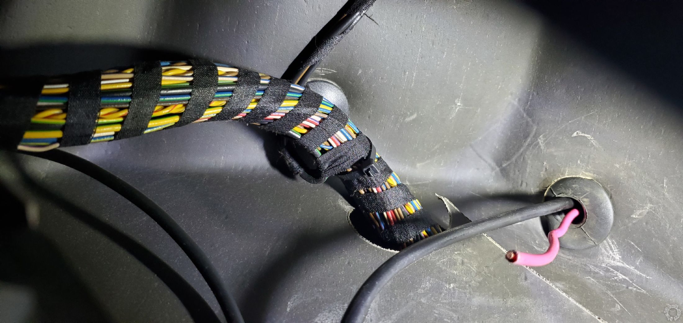
But how do I know which wire is which?
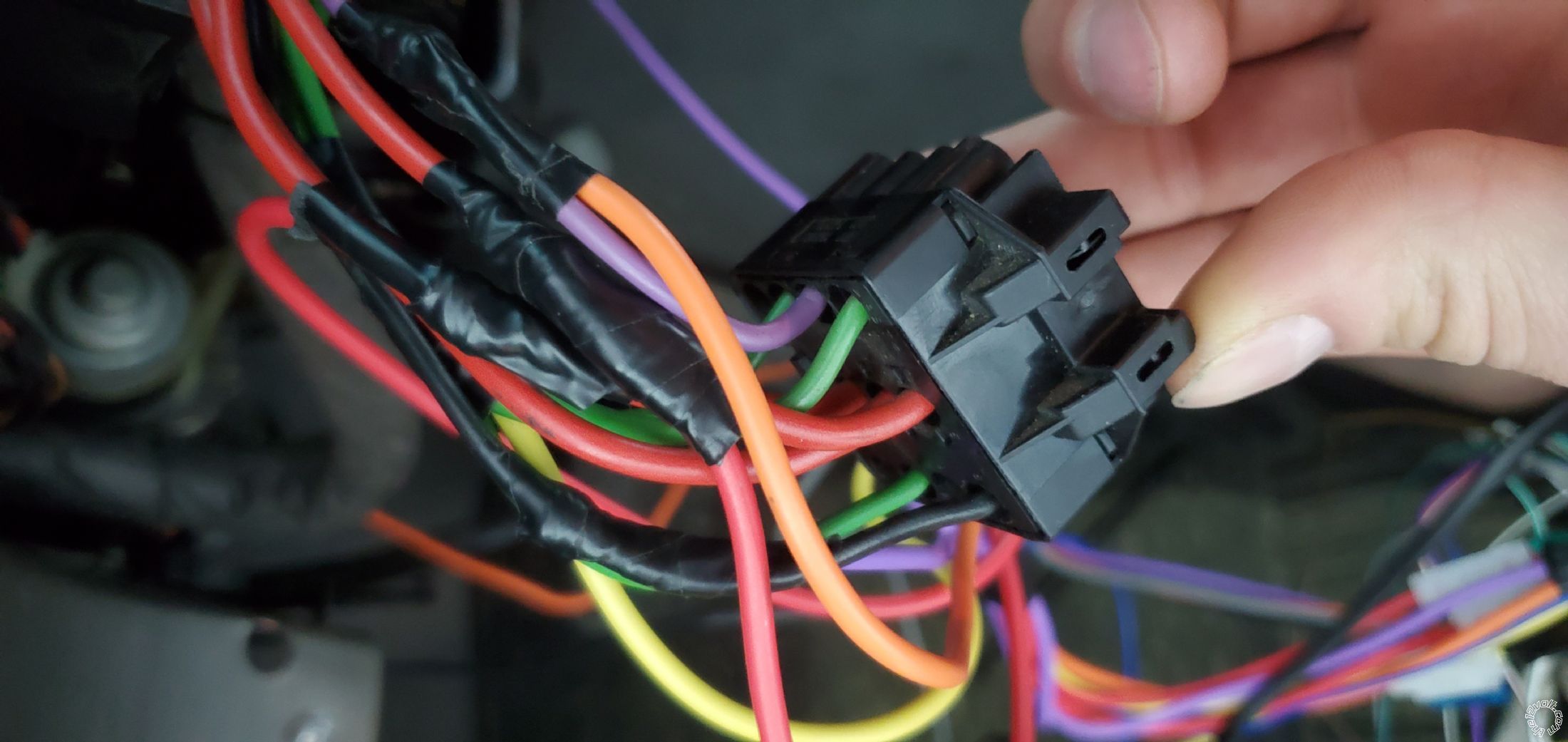
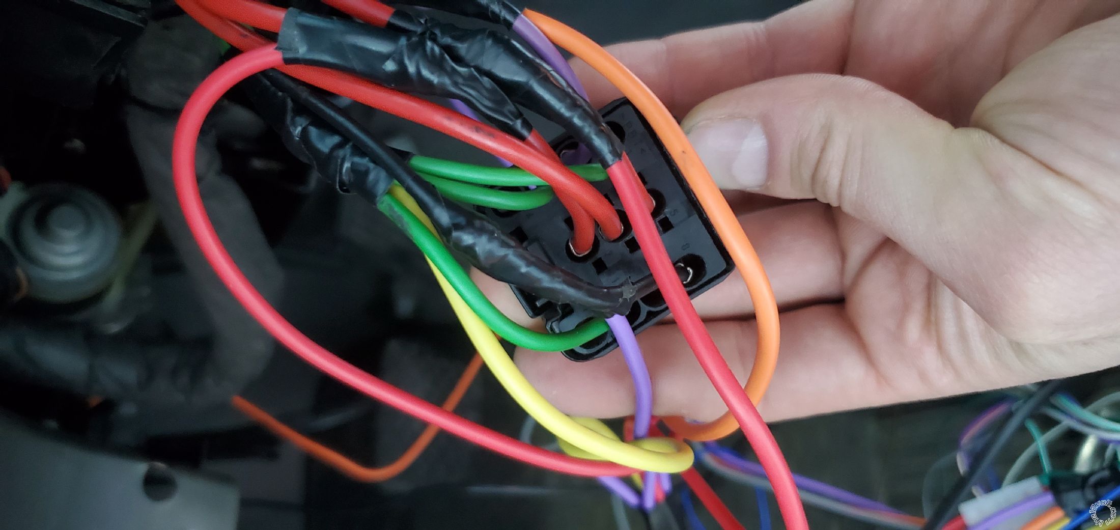
I was able to identify some connections and the pinout using https://www.newtis.info
But I can't even follow the wires from the connector because the connector blocks the wires
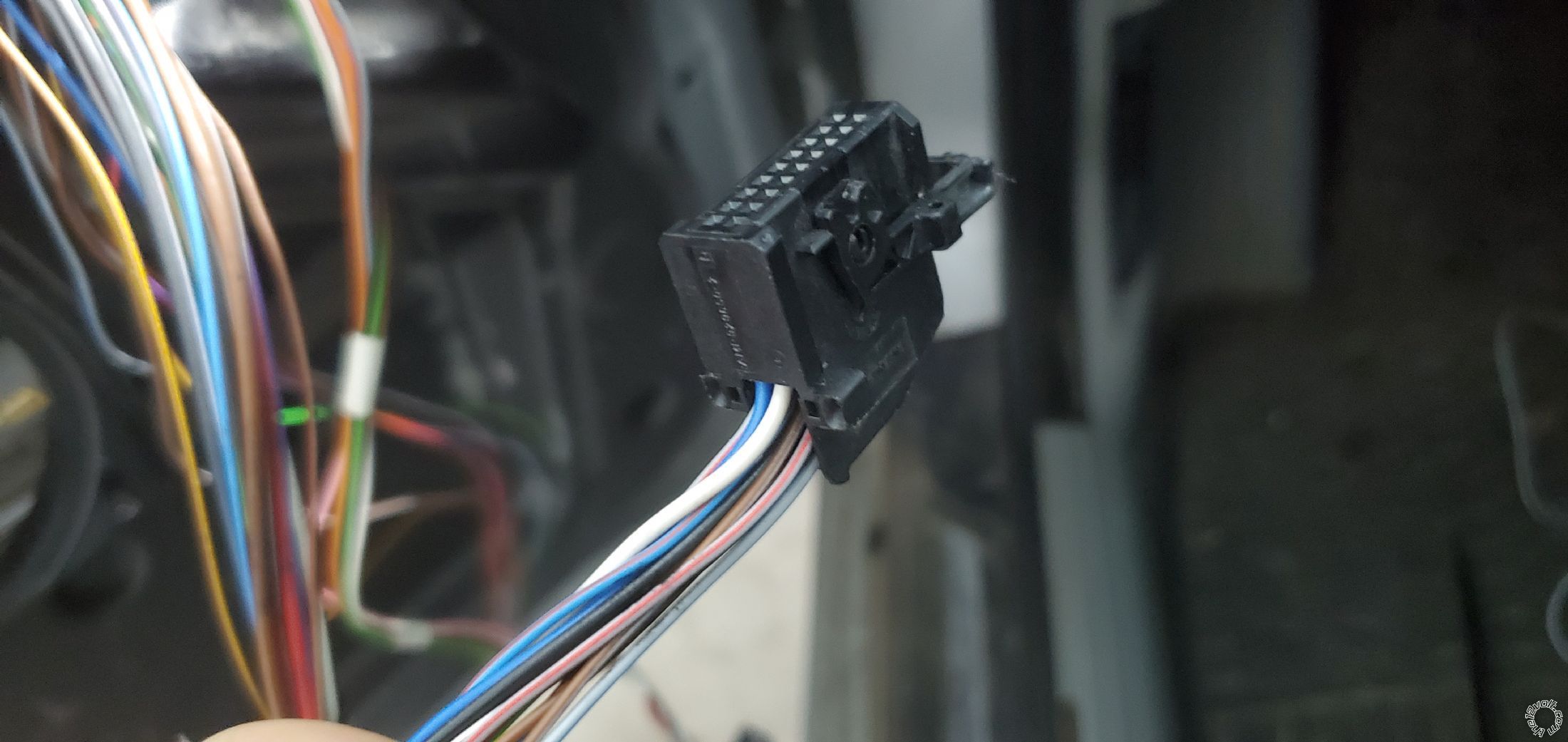
I wonder if anyone can help?
Replies:
Posted By: geepherder
Date Posted: October 29, 2019 at 2:57 AM
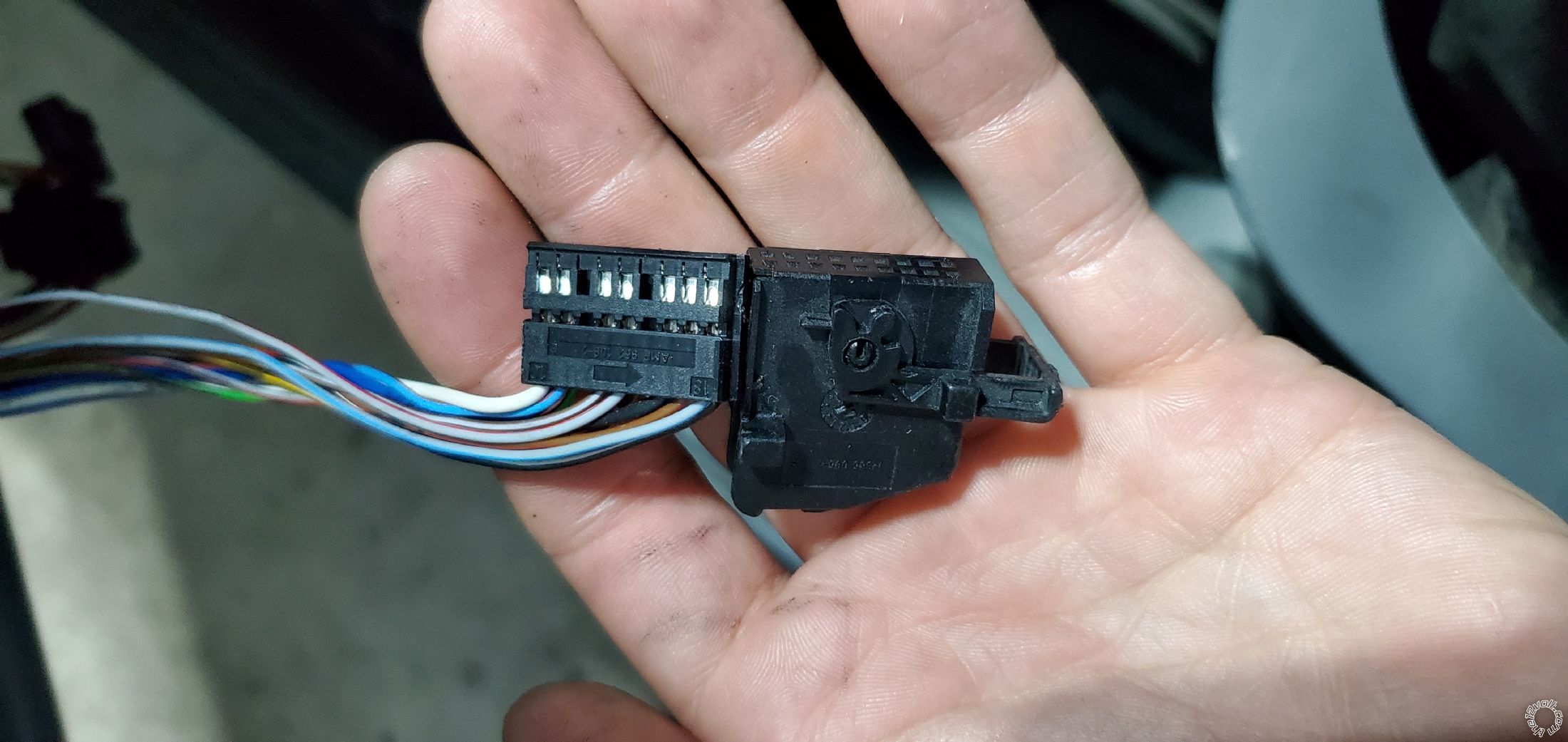
There may be a lock of some sort, but that connector will slide apart. The body will separate into two main pieces. The bottom end of the connector will slide out of the outer shell, exposing the wires inside which can then be depinned if necessary. You might try gently prying with a small screwdriver.
-------------
My ex once told me I have a perfect face for radio.
Posted By: silvercivicsir
Date Posted: October 29, 2019 at 11:42 AM
test light / multi meter is your friend. find the correct color wire, and test it's function.
Posted By: bmwe39528i1998
Date Posted: October 29, 2019 at 9:20 PM
Thanks for that!
You were right it separated
Copper what procedure do you guys use to test with a multimeter or test light to find the right wire? Sorry I'm a big noon in electronics.
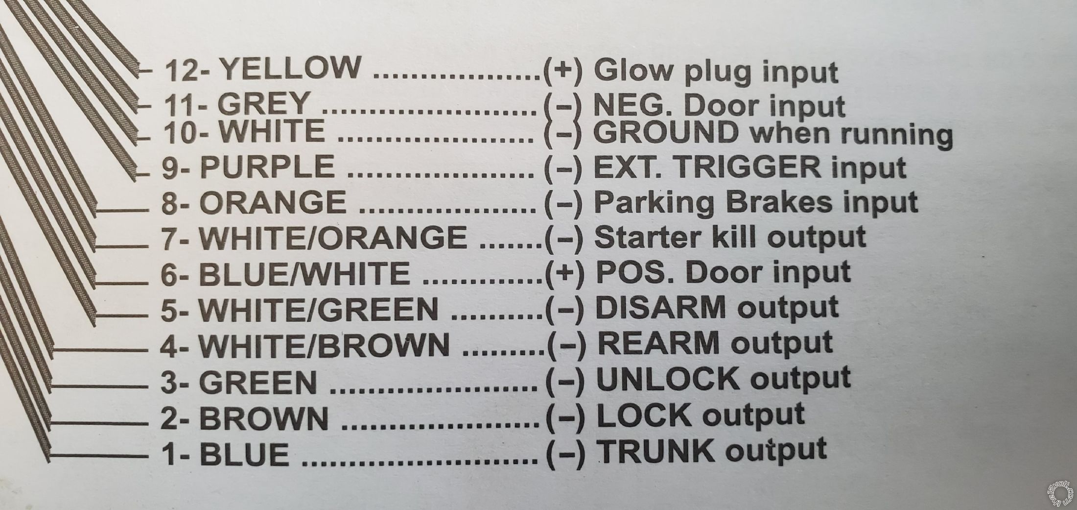
I'm kind of stumped with the 12 pin connector on the remote starter.
Can someone explain in layman's terms what this all means?
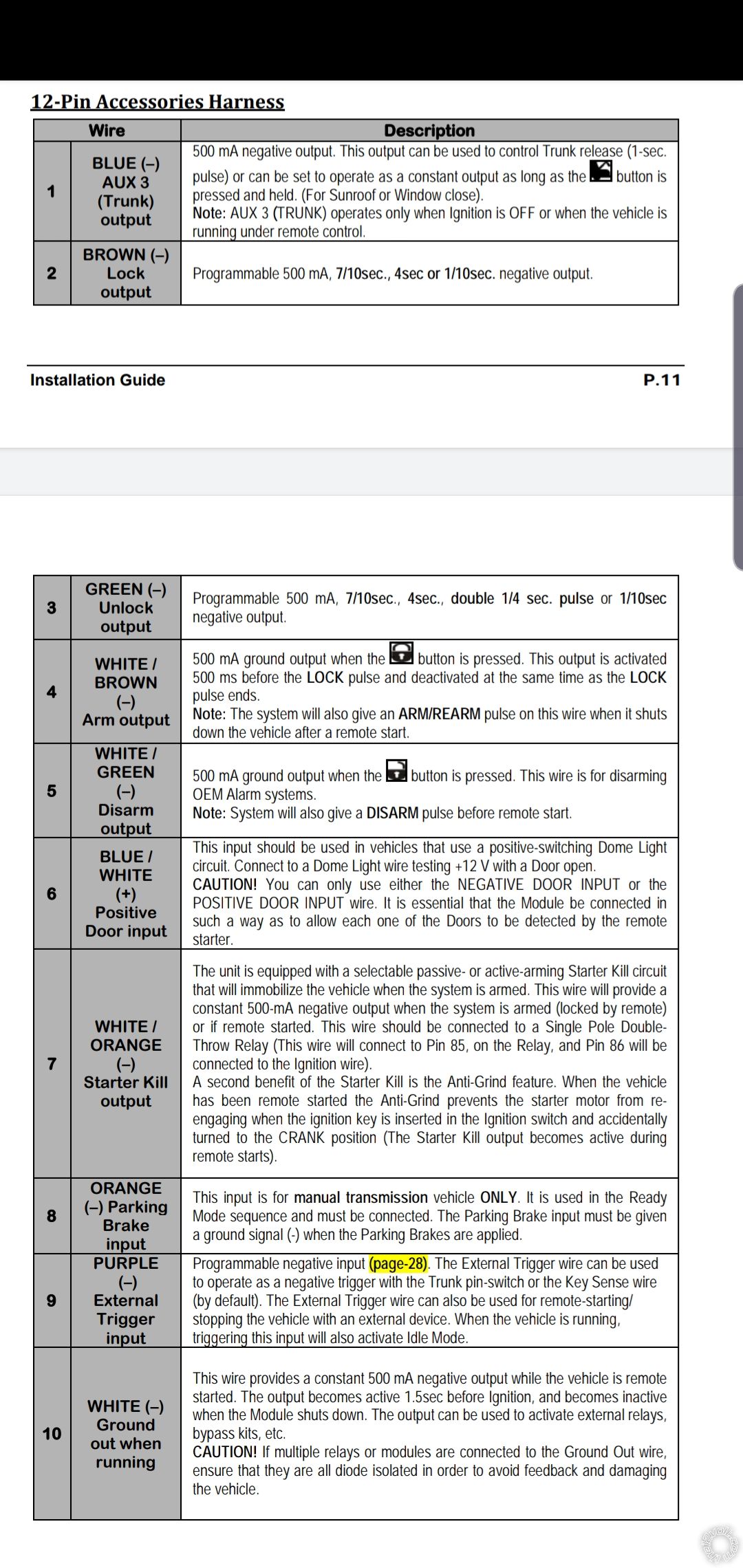
#1 is easy enough, trunk release, got it working!
#2 Do I connect it wherever? Don't know where it's supposed to go.
#3 seems like #2. What you guys do with these?
#4&5 seem to be for arming/disarming, I need to just find it on my car
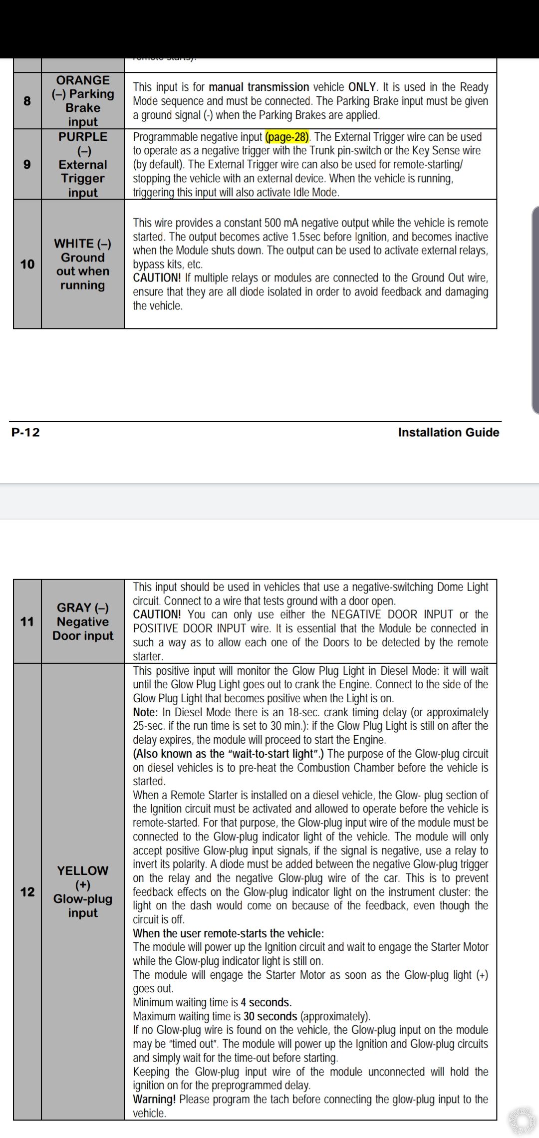
#6 Something to do with a dome light, but no clue what it does
#7 Starter kill switch, something to do with helping the car not get stolen. Again no clue what to connect it to.
#8 For manual transmissions, good to know I don't need this!
#9 Some kind of trigger, what can I do with it?
#10 Something similar to #2 and #3. What do people use it for?
#11 Like #6, something to do with dome light but negative rather than positive. Not sure of the difference.
#12 This is like #8, I don't have it so I don't have to worry about it:)
Once I figure out this portion I can do a write up on step by step instructions for E39 remote starter.
Posted By: geepherder
Date Posted: October 30, 2019 at 6:14 PM
Wiring information is available if you know where to look. You can go to https://www.bulldogsecurity.com/bdnew/vehiclewiringdiagrams.aspx and search for your vehicle. Also, the vehicle wiring section on this site is also helpful: https://www.the12volt.com/installbay/vehicles.html
Testing and verifying wires as silvercivicsir stated is important also. If you don't have a digital multimeter, I suggest you get a basic one. You can pick one up for cheap at Harbor Freight or Walmart. Here's some helpful information on testing wiring: https://www.commandocaralarms.com/info_using_a_multimeter.asp
#2/3 If you pull up your vehicle's wiring information, you need to run wires into the driver's door. You will also need relays to convert from negative to positive. Apparently unlock requires a double pulse as well (hopefully this is programmable on your unit).
#4/5 Used on some vehicles to arm/disarm the factory alarm. You may not need it.
#6 Connect to the positive door trigger wire at the dome light (blue/red). Verify this with a meter.
#7 https://www.the12volt.com/relays/starter-interrupt-diagrams.asp
#9 Connect to the trunk pin wire (brown/white) at the trunk pin.
#10 You can use this for your immobilizer bypass.
#11 Not used. ------------- My ex once told me I have a perfect face for radio.
Posted By: bmwe39528i1998
Date Posted: October 30, 2019 at 8:09 PM
Thank you for sharing the information and that extra link!
I've got a very good multimeter and actually use it as described on your other link.
While researching, I learned that for my car, it arms and disarms when the car is locked and unlocked.
Therefore #2 and #4 do the same thing as well as #3 and #5.
Pretty good considering I fried my door modules when I connected the battery in reverse by accident, so I dont have to worry about these wires.
Still, I connected the wires for lock and unlock but nothing happens when I press lock and unlock on the remote starter key fob.
Yet the key from the car does lock and unlock the rear doors, which is kind of confusing. I wonder where does the signal go from my car key if it's not in those wire in my driver's door?
#6 - where would you tap it? It says Dome light, but that would be too far. And it looks like dome light goes to the glove box, which is even further.
https://www.newtis.info/tisv2/a/en/e39-528i-lim/components-connectors/components/e-lights-electrical-heating-systems/lamps-electrical-heaters/e34-front-interior-reading-light/e4Z4hzR
https://www.newtis.info/tisv2/a/en/e39-528i-lim/UsziYBw
The wires going from my remote are just not long enough. Do I need an extra wire to run it all the way from my remote module to the dome light?
Is there really not another wire somewhere closer?
#7 looks like some kind of a hidden kill switch so that the car won't start when it's disarmed.
#9 Sorry do you mean to run the wire all the way to the trunk handle? Or connect it at the same connector as #1 but a different wire?
What does it do exactly? My trunk seems to be opening fine from the remote starter fob after I connected the blue wire #1
#10 Removed the immobilizer, life is easy (it's a parts car/winter beater)
Funny thing, even though my front door modules died and I removed them, I can lock/unlock the rear doors with the key fob.
I'm curious how it does that.
The central locking switch is not working
https://www.newtis.info/tisv2/a/en/e39-528i-lim/components-connectors/components/s-switches-encoding-plugs/switches-coding-plugs/s302-central-locking-switch/W9MZH4D 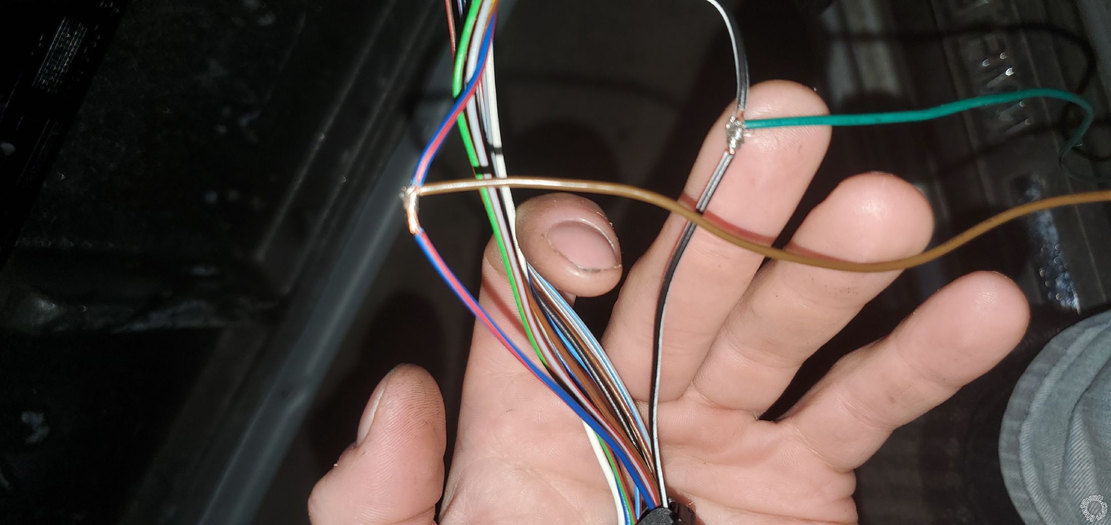
Then how come my car key can remotely lock and unlock the rear doors but my remote starter key fob won't do that?
Another super confusing thing.
On the 5 wires coming from the module, I don't seem to get any volts from #5 parking lights yellow wire.
I wanted to connect it to the parking lights behind the switch, but it's not giving me 12 volts.
Is this a problem with my module?
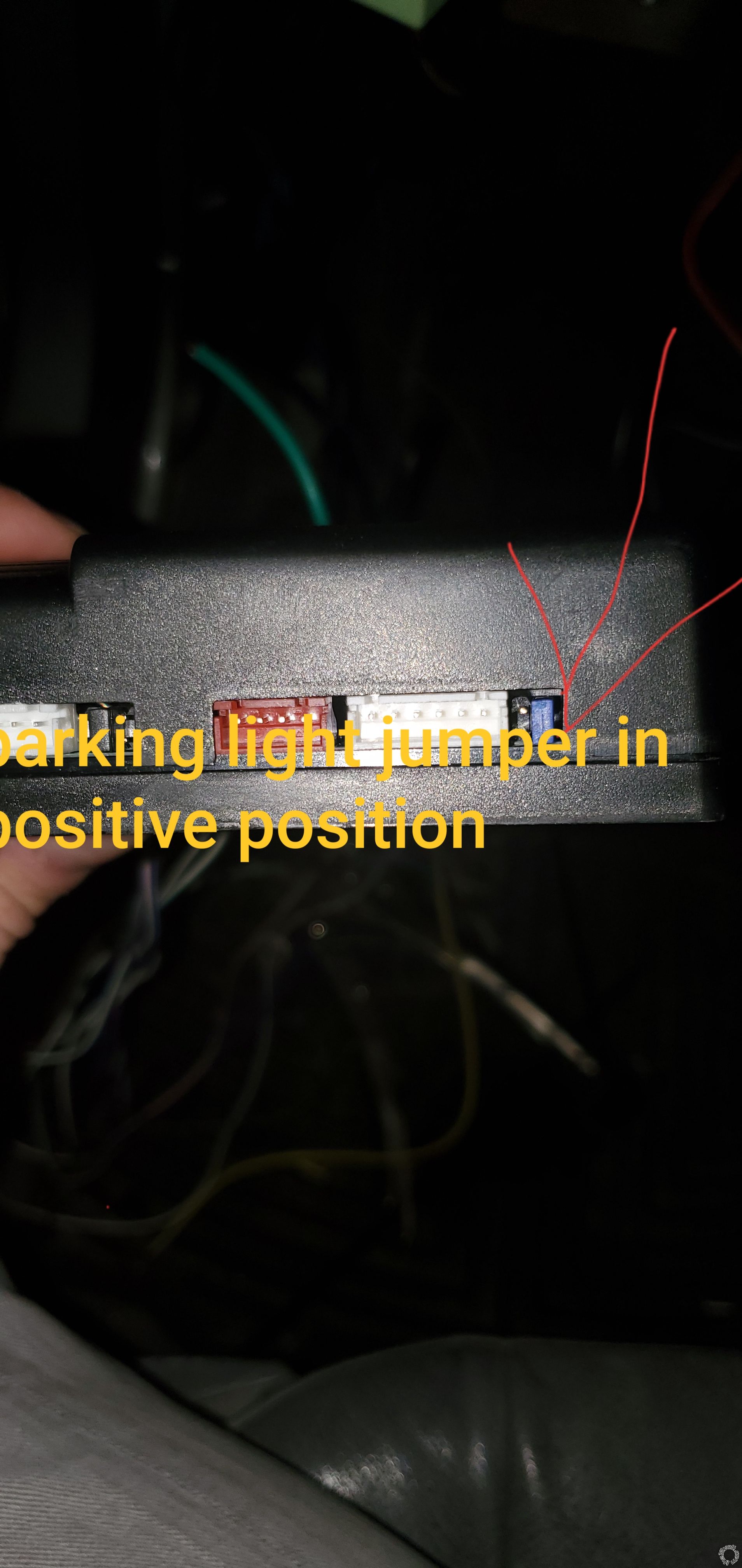
I've put the jumper to the "positive" in the back of the remote module.
I also tried setting the jumper to "negative" but no luck.
Am I doing something wrong here? 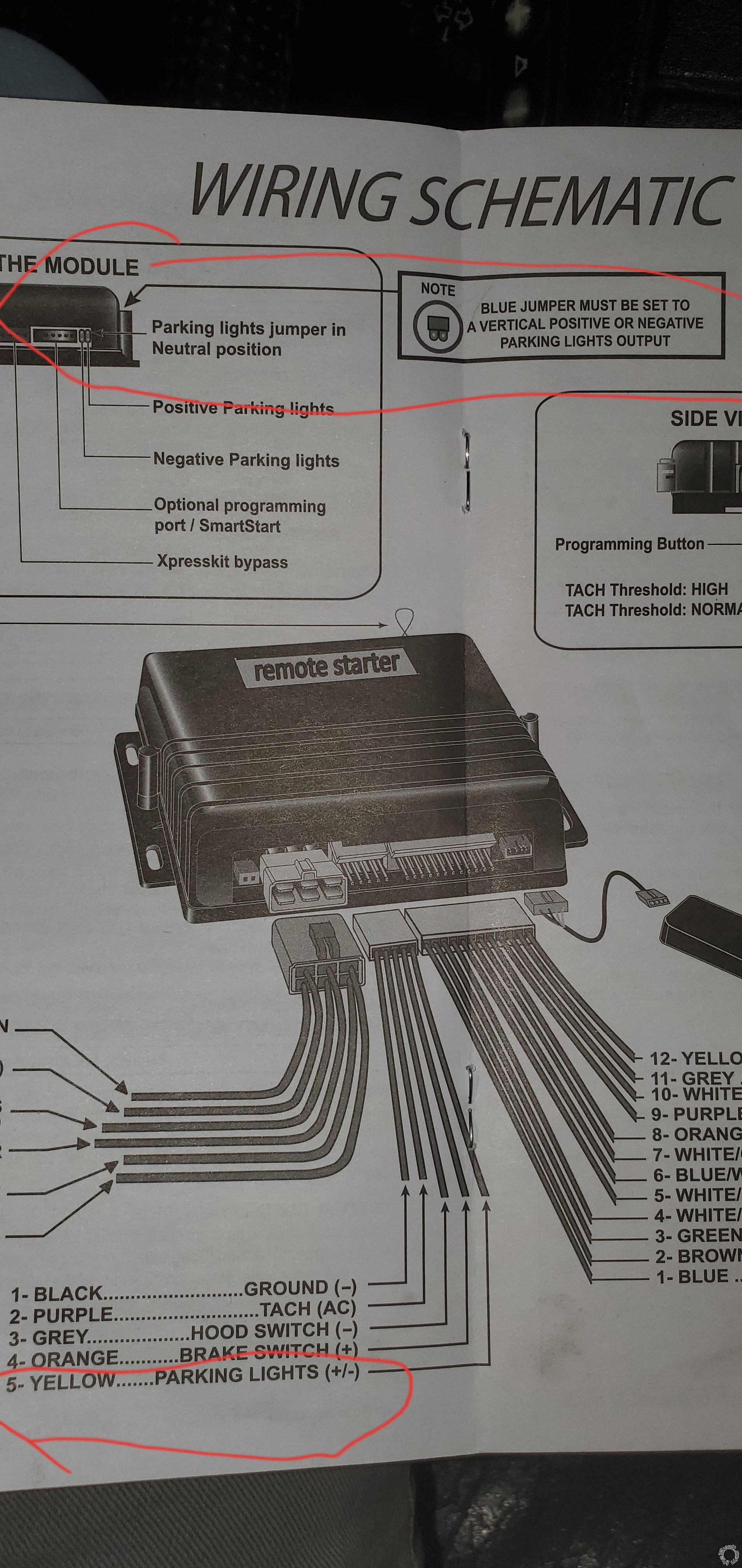
Posted By: geepherder
Date Posted: October 30, 2019 at 8:42 PM
Remote keyless entry is controlled by an RF signal through a different module (not as simple as connecting a couple wires). The front door lock actuators are driven directly from the door modules.
#6 You can extend the wires to wherever is convenient for you to connect.
#7 So the car won't start when it's armed.
#9 Connect wherever it's convenient for you. This senses when the trunk is open (or other sensor if you add one), to trigger the alarm.
https://diagrams.marktoonen.nl/DOWNLOADS/17044_5-SERIES_BMW%20PARKING%20LIGHT%20FLASH.pdf------------- My ex once told me I have a perfect face for radio.
Posted By: bmwe39528i1998
Date Posted: October 31, 2019 at 2:20 AM
Thanks again!
I think #6, 7 and 9 are not worth the hassle. Running wires all the way to the trunk and under the headliner just for the dome light...isn't worth the hassle.
What does the dome light do anyway? Lights up when you start the car from remote?
Thanks for the diagram, I've seen it from the website you shared previously.
Unfortunately I'm kind of stuck at the step of parking lights.
Well first of all I'm not getting the 12 volts I'm supposed to be getting from the yellow wire coming out of the remote module.
That means I cannot supply the relay with 12 volts. And if I cannot supply the relay with voltage, obviously nothing can happen.
Secondly I'm not getting 12 volts on the wire going to the parking switch
It says I should be getting 12 volts at the wire and I'm only getting 3 volts.
https://www.newtis.info/tisv2/a/en/e39-528i-lim/components-connectors/components/s-switches-encoding-plugs/switches-coding-plugs/s8-light-switch/Yr1fNkL
What gives? I mean the parking lights are working after all. Maybe something to do with the fact that I have no parking lights on the front but only in the back? In the front, I'm missing sockets for the parking lights. Gotta go to a scrap yard to pick up some. Got these headlight assemblies without parking lights
Posted By: geepherder
Date Posted: October 31, 2019 at 8:31 AM
After seeing the model on the pic you posted, I realize this is just a remote start, not an alarm. The dome light connection is to monitor when you have a door/doors open. Since you don't have a manual transmission, you can disregard this.
If the remote start positive parking light output is not working, try the negative output to control a relay. If that doesn't work, and since you don't need a transponder bypass, you could possibly use the ground-while-running (white pin 10) wire to control a relay for the parking lights. That way, you'd have visual confirmation that the car is running.
-------------
My ex once told me I have a perfect face for radio.
Posted By: bmwe39528i1998
Date Posted: October 31, 2019 at 3:58 PM
I'm really at a loss here...
No power from orange wire and no power from the white wire.
I also tried the green wire from fifth relay and no luck either. 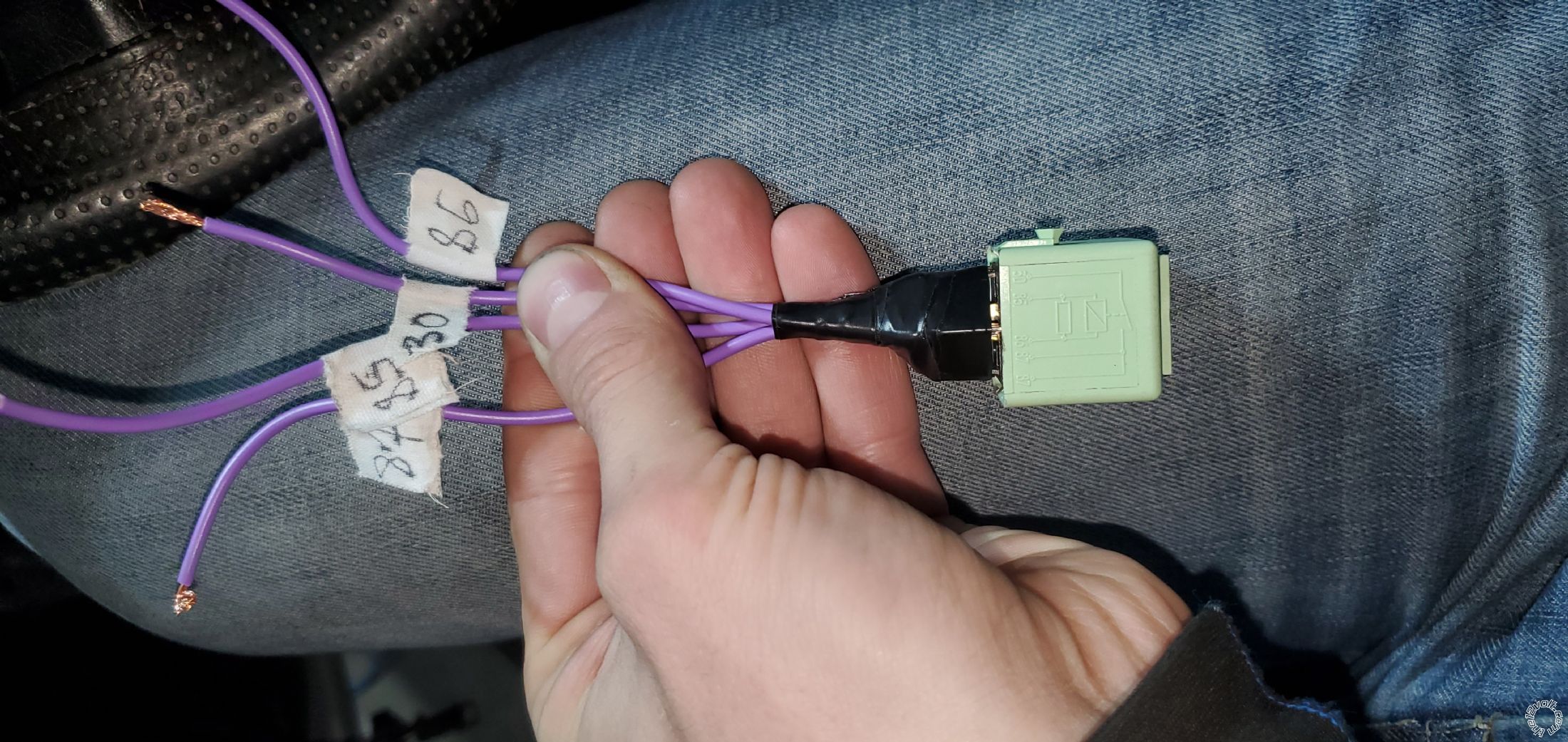 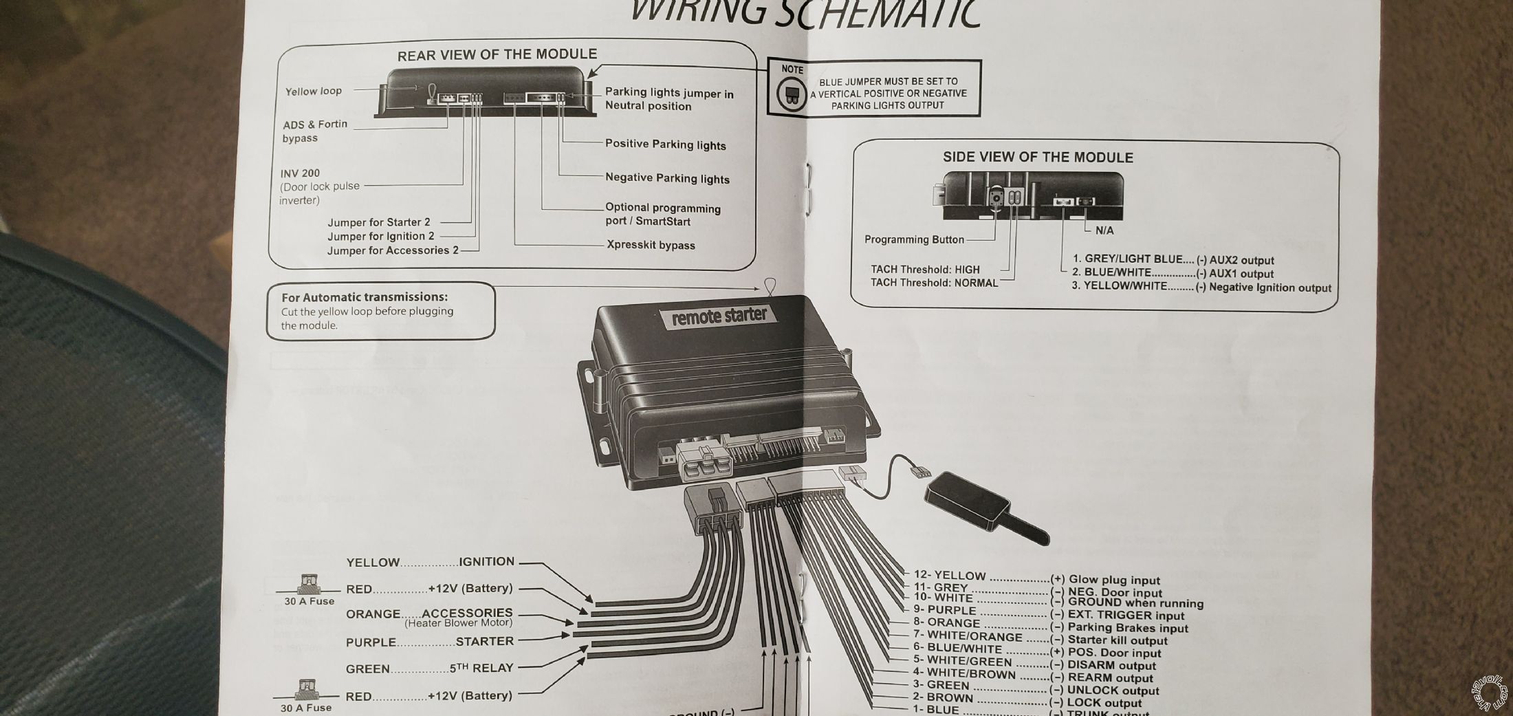
I wired relay terminals 30 and 87 in between the wire that activates signal lights. I connected terminal 85 to the ground wire on the parking light switch.
The I tried connecting all the wires I mentioned to terminal 86 to supply power and no luck. My parking lights stay on (since there's a break in the power wire).
I tried supplying power from a 12 volts charger and instantly the relay clicked and the parking lights went out.
I tried the same with using the power from the courtesy light and it worked as well.
So I know my connection and the relay are good.
Why am i not getting power from the remote module? Is it faulty? Did i wire something else wrong?
I tried disconnecting all the connectors from it and connecting back but still no luck.
Though the car starts just fine...
Posted By: geepherder
Date Posted: October 31, 2019 at 8:33 PM
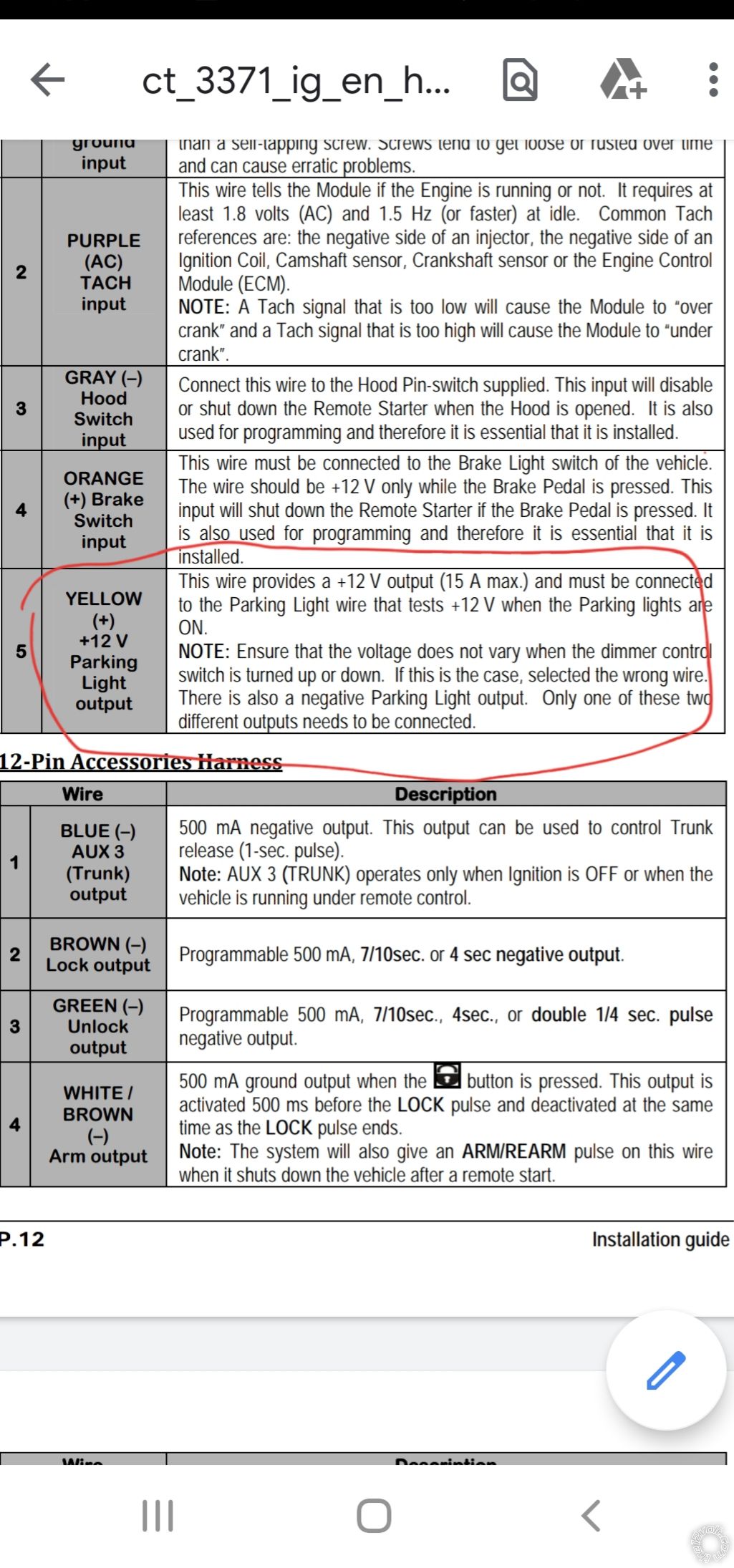
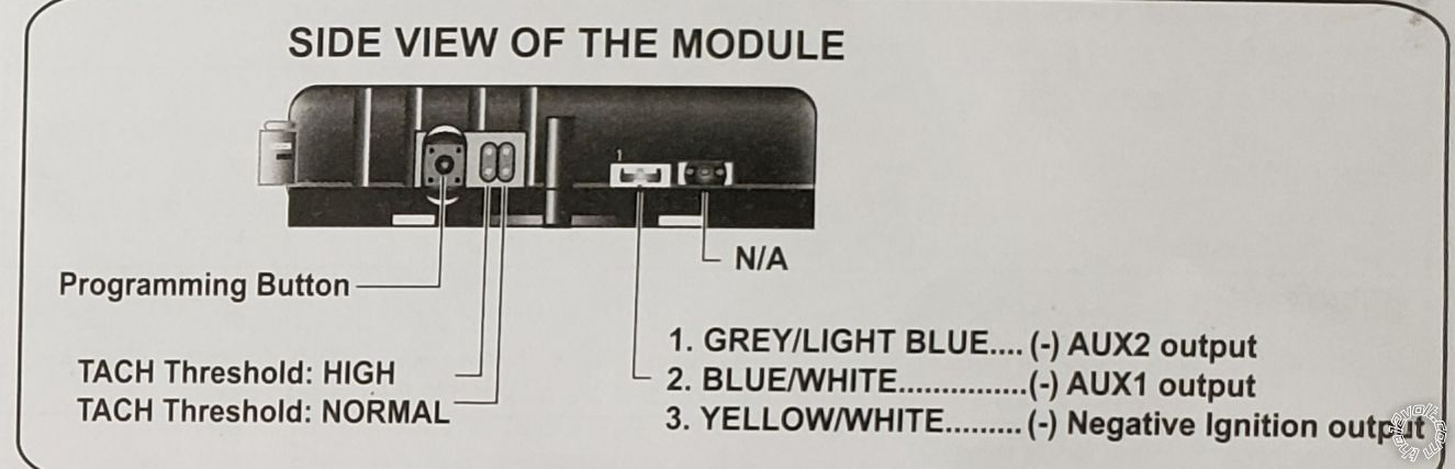
87A should be used instead of 87. This way your parking lights will be off by default. By orange wire, I'm assuming you mean the yellow wire is not putting out voltage. The white wire is negative and will not give you positive voltage. Do you have the jumper correctly positioned for the green wire (either accessory or ignition)?
Something I noticed on the picture of the manual you posted (not the one I found online), is the parking light jumper. Do you have this set in a vertical position (not the horizontal neutral position)? If not, this is likely your problem. The left position is for the negative output, the right position is positive.
-------------
My ex once told me I have a perfect face for radio.
Posted By: bmwe39528i1998
Date Posted: October 31, 2019 at 8:55 PM
On my relay it has two 87 pins but no 87a pins. Not sure if it's a huge difference but it works fine when I supply it with power.
Yes you're right, sorry I got confused with all these wires lol! It's the yellow wire, not orange.
I believe both jumpers are set properly.
I tried setting it in both positive and negative.
On this website it says the parking light is negative
https://www.bulldogsecurity.com/bdnew/vehiclewiringdiagrams.aspx
But either way I tried both.
But most confusing is that I'm getting 0 volts on yellow and green wires.
My multimeter is smart, even if I reverse probes, it will still show voltage with the negative sign in front.
But in this case I'm not getting any voltage output from the remote module, which is puzzling. Yet the car starts and the trunk opens from the remote
Posted By: geepherder
Date Posted: November 01, 2019 at 3:01 AM
If your relay has your parking lights normally illuminated and they go off when you put 12 volts to the trigger, switch to the "other 87" (which is actually 87A). Otherwise your lights will normally be left on, draining the battery.
Even though it shows negative for parking lights at the switch, it says see diagram (which is linked to the right). If they were working you could use either the negative or positive output since it's not getting connected to the car, but being used to trigger a relay which connects to the car.
If you have a ground connected to 85 of your relay, then you would need a positive output to 86 since a negative wouldn't trigger it. Since you can't get a positive output to work, connect 85 (or 86) to a constant 12 volt positive source, and connect 86 (or 85) to the negative output. Be sure to move your jumper to the negative output position.
-------------
My ex once told me I have a perfect face for radio.
Posted By: the12volt
Date Posted: November 01, 2019 at 7:27 AM
If the relay has two 87 terminals, you have a dual make relay, not an SPDT relay. -------------  the12volt Support the12volt.com the12volt Support the12volt.com
Posted By: geepherder
Date Posted: November 01, 2019 at 8:02 AM
^^ +1 what he said. I should have realized that. You still have other issues, but you need a SPDT relay. If it doesn't have an 87A it's the wrong one even though it looks the same.
-------------
My ex once told me I have a perfect face for radio.
Posted By: bmwe39528i1998
Date Posted: November 01, 2019 at 8:32 AM
Based on this link I think it's a Dual Make Single Pole Single Throw Relay.
If you look at the picture I posted, it has two 87 terminals and they both get connected to the 30 terminal when there's power to 85 and 86.
I can look if I have other relays, or I can order one online that has 87 and 87A terminals.
The biggest issue right now is trying to figure out why I'm getting no power output from the module where I should be getting 12v.
Is it possible I connected something wrong at the ignition switch?
You see, most graphs/tables I've looked at, they don't provide clear instructions.
Like this one only lists one red constant 12v wire and one green 12v ignition wire. I have 3 of each.
The instructions scattered on the internet vary to some degree. I followed what I thought made most sense.
Here it says to connect the 4 green ignition wires together. I only connected 3 because I have only 3 green wires.
For the constant 12 volts I have 3 red wires at the ignition switch and based on the picture of remote instructions, I only need 2 to power the module. So i connected both red wires separately from the module to the ignition switch. It looks like it doesn't matter what wire in the ignition switch I choose. I have 1 more (3rd) red wire on the ignition switch I didn't touch.
If I understood correctly, you're saying I should disconnect the ground wire of the parking lights from the relay.
Instead, I should connect constant 12 volts (found somewhere in the vehicle, maybe I can take it directly from ignition switch) to 85 relay pole and connect the yellow wire to 86 pole, having switched the jumper to "negative" on the module.
Let me try this.
I honestly don't care too much for the parking lights on this beater 528i, but it's annoying the hell out of me that I cannot figure it out. I also want to write up a good tutorial with pictures and footnotes, not just bare bones "Power Lock: BLUE/RED" without really knowing what the wire looks like and where exactly to find it.
Posted By: bmwe39528i1998
Date Posted: November 01, 2019 at 9:47 AM
I'm no pro but I'm leaning toward a faulty module...unless my connections are so wrong they messed up the module in a way it doesn't give proper outputs.
I changed parking lights jumper to negative and powered up the relay on terminal 86 with 12 volts from courtesy lights (easiest to access since my door is taken apart).
I closed the circuit with the yellow wire in terminal 85 and nothing happened.
I double checked the ground wire from the starter module and it's grounding properly.
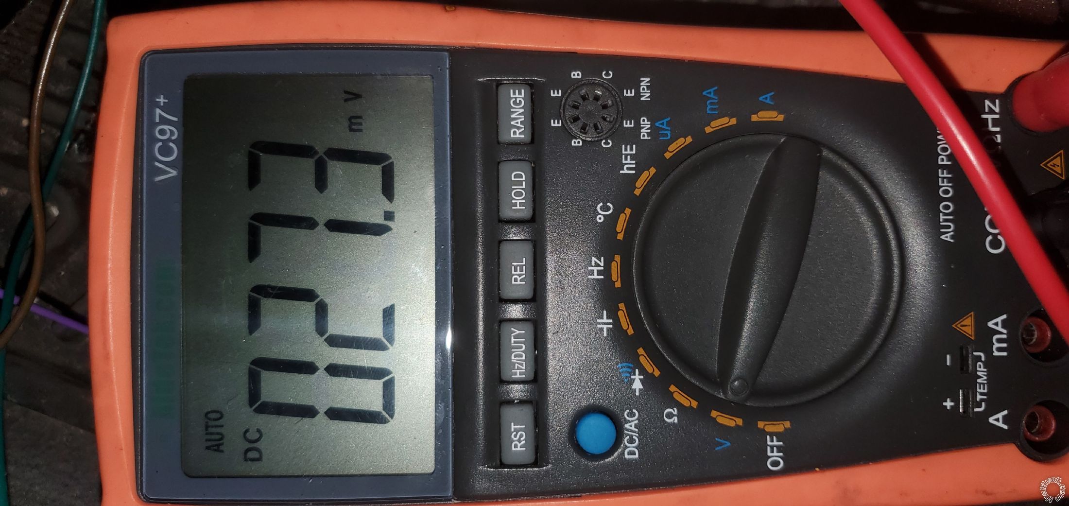
I tested all the other wires on this connector just in case. By default I tested without a key in ignition and then turned it to "on" (all the way forward before cranking) to see if things changed
1 - ground
2 (tach) no voltage (001.4 m V). With key in "on", 9.22V
3 (hood pin) 4.68 volts
4 (brake switch) -000.3 m volts. Key on, 017.5 m volts. Brakes applied - 12 volts
5 (parking lights) around 016.2 m volts key on, 029.0 m volts
I found the correct relay you guys suggested 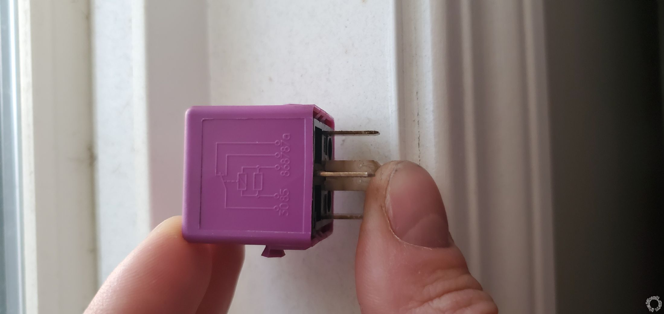
But with the current state of affairs it's of no use
Posted By: bmwe39528i1998
Date Posted: November 01, 2019 at 10:33 AM
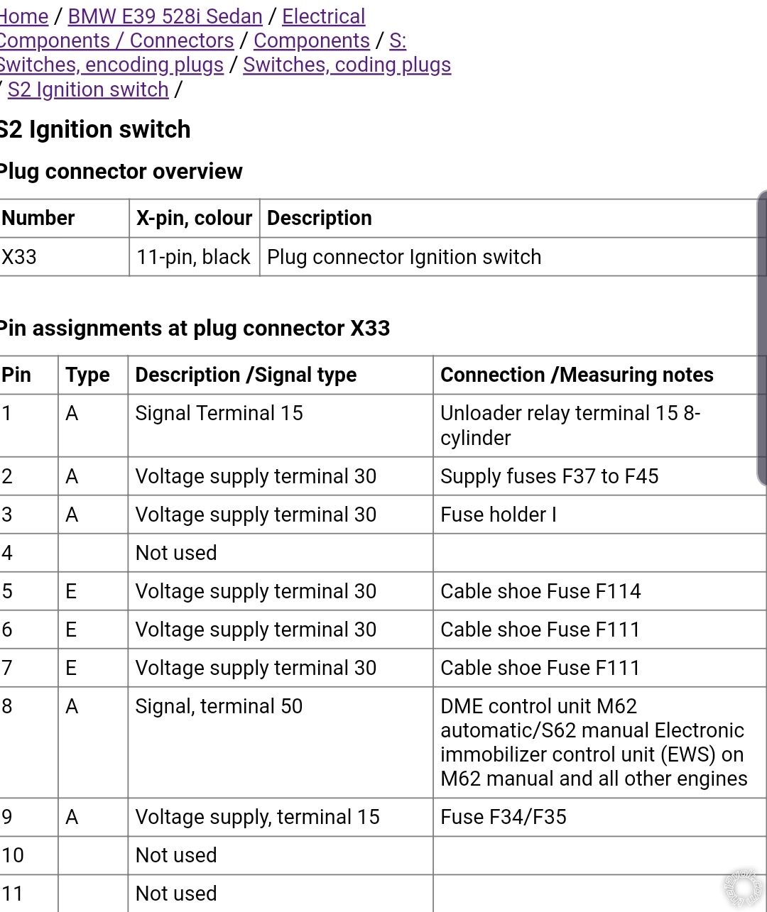
This is my ignition switch pinout
Pin
Differences:
I've got nothing on pin 9, though the picture says "voltage supply"
I've got a green wire on pin 10, while it's empty on the picture.
I don't know why it's different.
None of them seem to match up exactly to mine
https://www.newtis.info/tisv2/a/en/e39-528i-lim/components-connectors/components/f-fuses/fuses/f35-fuse/q-S2
None of them say which wire is ignition, accessory etc.
My ignition switch connections:
Pin 1, 3 and 10 are green wires that I understood are all ignition.
I connected the 3 of them together to the yellow (ignition) wire from the module.
Pin 2 is a purple wire I understood to be accessories, so I connected it to the orange wire on the module.
Pins 5, 6 and 7 are all red power wires, 12 volts constant. I spliced wires on pin 5 and 7 and connected them separately to 2 red wires from the starter module. I left red wire on pin 6 intact.
Pin 8 is a black starter wire, so I connected it to the purple starter wire on the module.
Pin 9 is empty
Pin 10 I already covered
Pin 11 is empty
I did my best given some confusing instructions.
For example,
this is showing the starter wire as black/yellow. Mine is plain black.
Another confusion, it shows ignition 1 as green and ignition 2 as purple, but my purple wire is accessories I think.
And I have 3 green wires in total.
The website doesn't list a wire for accessories and shows it N/A, which I figure is incorrect.
The website shows only 1 wire as green for ignition, while I have 3 green wires. And of course the bulldog security website doesn't tell the wires by pin number, so, one is left to guess...
I wish they said, green wire on pin 1 arc.
Now on the 12 volts.com it's also somewhat incorrect. Granted they're talking about e39 530i, while mine is 528i
They only account for 2 green wires while I have 3. At least they label both green wires as ignition, in contradiction to bulldog security website which labeled one green as ignition and 1 purple as ignition.
Both accessories and starter are shown as black/yellow, which is incorrect.
If this was the case, how would one know which black/yellow wire is starter and which is accessories?
I definitely only have 1 black wire. So hopefully it's the purple wire on my ignition switch for accessories and I wired it correctly.
For this reason I was doubting a little bit the way I connected the main wires on the first connector and thought they could cause problems on the other wires on my second connector.
Posted By: geepherder
Date Posted: November 01, 2019 at 10:54 AM
I just saw your module only has one parking light wire, not a separate positive and negative like the online manual I found. Yes it's likely that output on your unit is bad. Have you tried using the ground-while-running wire (white wire pin 10) to trigger the parking lights?
I would have kept each of the ignition wires powered separately.
The reason for testing wiring is to verify before connecting. Then it doesn't matter if the colors are somewhat different. The wiring information you find is just a reference and a good place to start. I do agree with you that pin number/location would be helpful.
-------------
My ex once told me I have a perfect face for radio.
Posted By: bmwe39528i1998
Date Posted: November 01, 2019 at 11:18 AM
Correct, just got one wire.
This is my remote.
Sorry what do you mean by "using the ground-while-running wire" ?
Didn't see your edit.
Yes I tried the white wire #10 as well, it's not doing anything, no voltage as well.
Posted By: bmwe39528i1998
Date Posted: November 01, 2019 at 11:29 AM
I guess it's time to exchange the module...How unlucky can I get, getting a bad module on the first try lol.
Is the module paired to the antenna?
Just to know if I only need to exchange the module separately and can keep the antenna I already mounted?
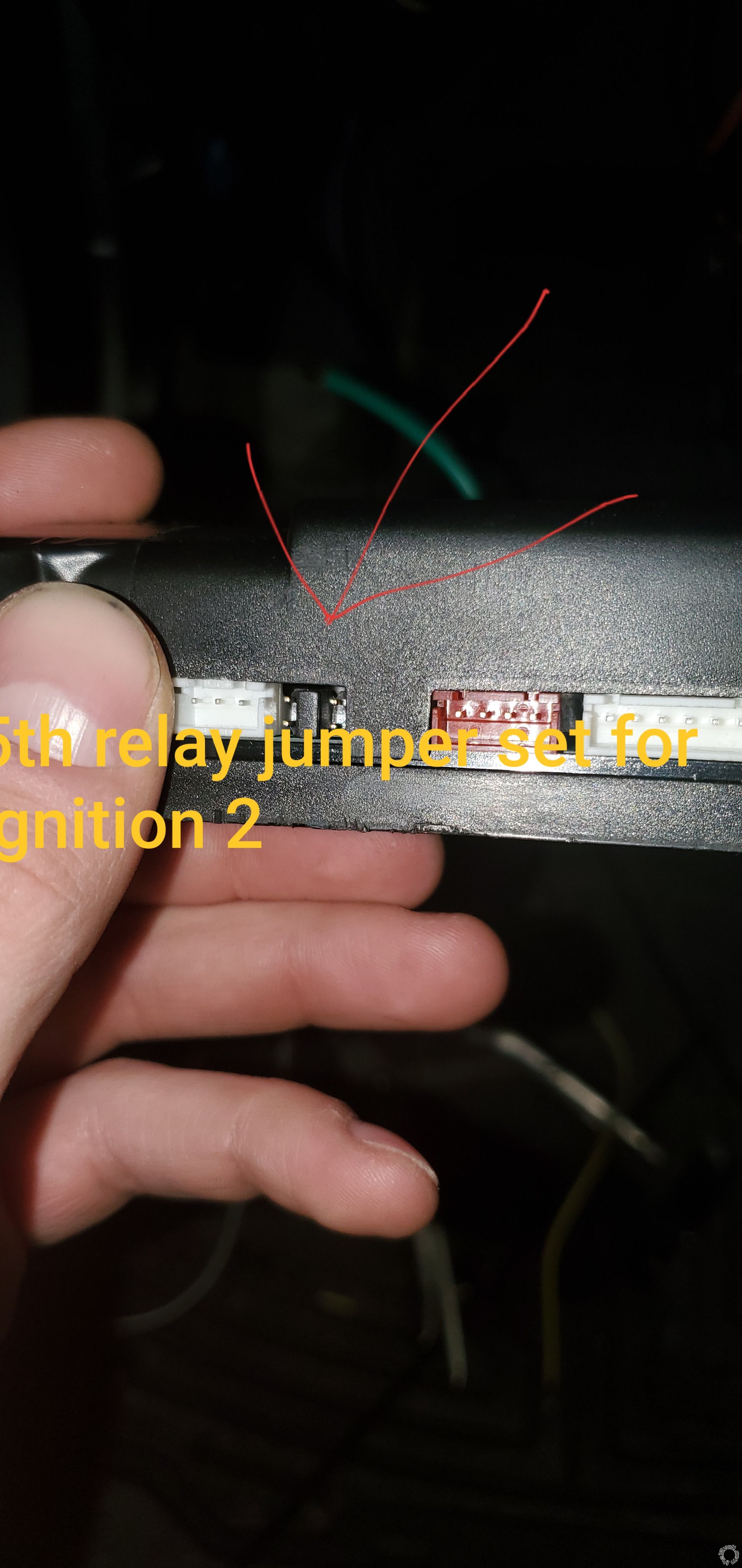
How would you power 3 ignition wires separately? There is only one output wire from the module (yellow wire). I could repurpose the 5th relay wire by placing the pin in the middle. Thay way I would have 2nd ignition output.
But what about the 3rd wire then?
Posted By: geepherder
Date Posted: November 01, 2019 at 4:54 PM
The white wire (pin 10) should show a ground while remote start is running. Touch your red meter lead to a positive 12 volt source and your black meter lead to this wire. If your meter reads 12 volts during remote start, you should be able to use this wire for the parking light relay. That would still give you visual confirmation.
You should be able to swap modules. I've never used that brand, but don't see why not.
As far as powering the second ignition wire, yes, use the green wire ensuring the jumper is in the right place. The third wire will require a separate relay, triggered by the negative ignition output wire (yellow/white in the 3 pin harness).
-------------
My ex once told me I have a perfect face for radio.
Posted By: bmwe39528i1998
Date Posted: November 02, 2019 at 12:38 AM
Thanks for your help.
I exchanged the modules and was finally successful.
The guy didn't think the module was to blame but still exchanged it.
Instantly everything worked right.
Powered the relay with the yellow wire, parking lights worked right away as they should.
I programmed the car to run for 25 minutes instead of 15 :)
I set the jumper to ignition and connected one of the 3 wires separately with the 2nd ignition from the remote module.
Now I only have 2 ignition wires connected together with the remote module wire.
For the 3rd wire and relay I'm not sure I understand you.
Are you talking about this 3 pin?
What's my connection setup with the relay. Do I put terminals 30 and 87a between the ignition wire going to the ignition switch, use yellow/white wire for ground and tap another ignition wire for positive?
Now the only thing I wanna do before putting everything back together is somehow activate the heated seats and steering wheel.
I still have a bunch of wires on the 12 pin connector. I only used 1 for trunk. But looks like they're all negative.
I'm thinking what I can use to activate it. I don't know if it needs a constant power or just a pulse to turn it on.
I need to think of some kind of a signal that activates the switch and then disengages the power.
This is a special case compared to all the wiring I did. It needs to be activated and then it works for a while before it shuts off and needs to be activated again. Kinda like the starter
Posted By: geepherder
Date Posted: November 02, 2019 at 4:30 AM
For the third ignition wire, yes, that negative wire in the 3 pin harness will go to 85 of a relay. 86 and 30 will connect to a constant 12 volt positive source. 87 (not 87A) will connect to the third ignition wire.
For the seats, you'll need to prove around with your meter and see what kind of signal is needed and go from there.
-------------
My ex once told me I have a perfect face for radio.
Posted By: bmwe39528i1998
Date Posted: November 02, 2019 at 10:01 PM
I took my panel apart and cut off the connector with the switch to test it.
Not quite sure how it works though.
I tried testing resistance between all the wires while pressing the button but wasn't able to figure out which wires activate the button.
I found this picture online
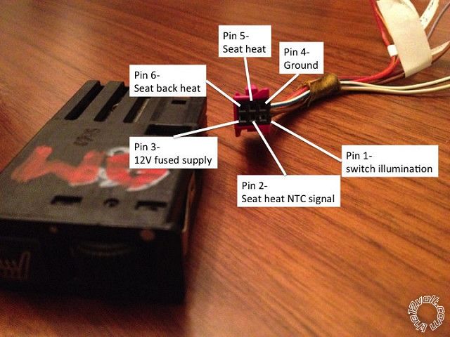
Everything is the same on my connector except mine doesnt have rear heated seats.
Once I removed the connector, I used 12 volts wall charger to supply pin 3 with power, and the light on the button came on.
So I'm thinking that when I press the button in my car, the circuit closes and the seats are heated for some time. After a while they're programmed to turn off so the power gets shut off.
I figure in this case I simply need to provide continuous power to pin 3 and it would activate the heating.
I'm not sure what pin 2 is for.
But I would've expected to have unlimited resistance between ground and power wires that went to 0 once I pressed the button.
If I can't figure it out, maybe I would connect directly to the heater connector under the seat and add an extra switch to turn it off once I'm inside the car after in warmed up.
Posted By: geepherder
Date Posted: November 03, 2019 at 6:14 AM
Rather than testing for resistance with it disconnected from the vehicle, I'd test for voltage in the vehicle while it's powered on. Backprobe each wire and test from a known reference (either ground or 12 volts positive).
Get a baseline without any buttons pressed, and make note of your readings. Then test while pressing a button. Repeat this for remaining buttons if you have more than one.
-------------
My ex once told me I have a perfect face for radio.
Posted By: bmwe39528i1998
Date Posted: November 03, 2019 at 1:15 PM
Good thinking! This worked.
I connected multimeter negative probe to the ground wire on the connector and then tested all the wires with button off and on.
The only difference was on pin 5 wire (heat seat).
It went from 0 to 12 volts.
Now pin #3 always had 12 volts and 2 other pins had 3.5 and 5 volts.
So I guess when I press the button, 12 volts from pin 3 get transferred to pin 5.
Maybe I can put a relay in between pin 3 and pin 5 and activate it by wire 10 from my remote or by negative ignition output?
I'm trying to think of a way that I can still use the button to turn off/on the seat heat.
Posted By: geepherder
Date Posted: November 03, 2019 at 8:39 PM
When you release the button, does pin 5 go back to 0 volts, or does it stay at 12 volts? This will tell you whether you need a momentary or a latched output from the remote start unit.
In order to connect pins 3 and 5, one will connect to 87 and the other to 30. 12 volts constant connects to 86 and 85 to your negative aux output. Be sure to program accordingly (pulsed or latched).
-------------
My ex once told me I have a perfect face for radio.
Posted By: bmwe39528i1998
Date Posted: November 03, 2019 at 10:06 PM
When I click it once, it lights up and stays on with 12 volts. If I press it again, it turns off and goes to 0 volts. Actually I'm not even sure if it turns off automatically or not, I can't remember.
I'm actually not sure if that means I should program it as latched or pulsed. I guess latched so that the relay closes and the supply of power is continuous.
I figure I can take constant 12 volts from pim 3 wire?
I'm going to try this tomorrow and report back to supply terminal 85 or 86.
I will try to incorporate rear defrost as well.
|