Hello. I have DEI "rattler II" alarm system in my 2000 s-10 xtreme. I have manual locks now and I would like to instal power locks. I have 2, 2 wire plungers now, and 4, 5 prong relays. Here is a pic of my alarm, and the wires. I was just wondering how I could add power locks to this system so that when I arm/disarm the system it will lock,unlcok the doors. Thank you for your help.


If you are using 2 WIRE Actuators:
The 2 Wires will need to Alternate Positive & Negative to make the Plunger go IN or OUT.
You will need:
2 SPDT RELAYS: ( Be sure they are Single Pole Double Throw Relays )
Lock & Unlock from Alarm ONLY
Relay 1
LOCK:
PIN 87 = 12 Volts ( + ) Constant
PIN 87a = GROUND
PIN 30 = wire to Positive ( or IN wire ) side of Actuators
PIN 85 = Negative Lock Output from Alarm
PIN 86 = Constant 12 volt ( + )
Relay 2
UNLOCK:
PIN 87 = 12 Volts ( + ) Constant
PIN 87a = GROUND
PIN 30 = wire to Negative ( or OUT wire ) side of Actuators
PIN 85 = Negative UnLock Output from Alarm
PIN 86 = Constant 12 volt ( + )
-------------
MO
Don't Learn from Others Mistakes
You Might Be the One That Knows.
If your Alarm Does NOT have Door Lock Outputs ( which I don't think the Rattler II does ):
There are a few ways you can still Lock & Unlock with using the Outputs from your Alarm.
You could use a Doorlock Pulse Creator, like Peripheral sells .....www.peripheralelectronics.com
OR
https://www.the12volt.com/doorlocks/page4.asp
| Single Pulse to Lock and Unlock |
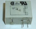
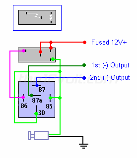
Using a mechanical latching relay like the PCB lacthing relay pictured below on the left and an SPDT relay, you can use a single negative output to alternately lock and unlock the doors. The mechanical latching relay only requires it's coil to be momentarily energized to change and maintain the opening or closing of it's contacts. The SPDT relay will provide a dedicated negative output for lock when the coil is energized and a dedicated output for unlock when it is not energized.
Remember, this is NOT the safest way to Lock & Unlock your vehicle.
Having a Unit with a designated Lock & Unlock built in is far more safer. |
-------------
MO
Don't Learn from Others Mistakes
You Might Be the One That Knows.
Thank you for that very helpful info. I have determined that my alarm dose not have the necessary outputs for the locks. I just have a few questions about the diagram posted above. First, where exactly would I connect the "1st (-) output" and the "2nd (-) output to? Second, where dose #85 off the SPDT relay connect to. I see one end of it goes up to the latchin relay, but the other end connects where? I am sorry to bother anyone with my ignorance in this area. I greatly appreciate your help.
PIN 85 would be a GROUND from either a Push Switch ( like a Valet Switch ) and / or the PCB Latching Relay.
What Outputs are listed on the back?
-------------
MO
Don't Learn from Others Mistakes
You Might Be the One That Knows.


