power seats controls w transistors
Printed From: the12volt.com
Forum Name: Relays
Forum Discription: Relay Diagrams, SPDT Relays, SPST Relays, DPDT Relays, Latching Relays, etc.
URL: https://www.the12volt.com/installbay/forum_posts.asp?tid=123069
Printed Date: May 09, 2026 at 5:40 PM
Topic: power seats controls w transistors
Posted By: kullakra
Subject: power seats controls w transistors
Date Posted: August 11, 2010 at 3:12 AM
Hi. I am new to this forum and not English speaking so my spelling may be a little off.
I have some questions about controlling motors in power seats. I have two comfort seats from a BMW e60 and they are originally controlled by can bus and the modules is fitted under the seats.
I have semi elictric seats in my e60 and if I change to the new seats I have to go to my dealer and reprogram the car to get the power seats to work. And rewire the can bus too. But I wonder if there is other ways to do this.
If I sell the car I want to keep the seats for my old car so I need to rebuild the controls.
So what I want to do is use small joystick controls to control relays that change polarity to the actuators and also to control the valves in the lumbar support. The joystick control cannot handle the current to operate the relays so I have to use transistors I guess.
I need help to dimension this transistors, resistors and, if there need to be diodes on the relays, the type of diodes. I think the joystick can handle about 20mA. I will use small relays fitted on a card.
The old seats have a switch that controls the two motors directly, so it should work to tap power from that cables.
I have drawn a layout and would appreciate opinions about if it can be done.
Thank you in advance as we say in Sweden. 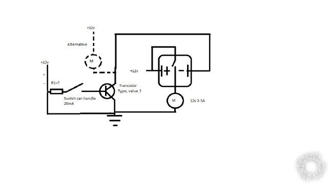 ------------- No reason not to try
Replies:
Posted By: oldspark
Date Posted: August 11, 2010 at 5:53 AM
Damn Swedes - you are worse than Turnips!
Since you are using then a switchers (on-off) and not analog, I reckon power FETS (MOSFETs) are much easier.
These can handle several Amps and are voltage switched (rather than transistors which need current and have a gain - ie, 20mA joystick to 5A = 5/0.02 => gain > 250 which is 2 transistors - say gains of 30 & 10 = 300; though <20mA to a >250mA relay coil is easy enough).
And MOSFETs that handle 60A can be as cheap as a few dollars.
How's that sound - one MOSFET to switch the motor direct from the joystick?
Although since polarity reversal is required, maybe a DPDT relay instead.. or as well....
But please confirm:
- the joystick is a switch type (not analog resistive);
- you don't mind +12V or GND switching (of the joystick)?
[ LOL! As I write this I am watching the TV music show "Spicks & Specks" on my PC. They mention Sweden's music exports - like Blue Swede, Abba, .... Meanwhile I think of Mikael Rickfors, Revanche (Kjänn Draget), Driller Killer, not to mention Refused! ]
Posted By: kullakra
Date Posted: August 11, 2010 at 6:32 AM
Hi!
Great you know some about Swedes! We had a culture-collision when my girlfriends relatives from Perth visited us som years ago. We found out we really didnt know anything about Australia and they knew very little about Sweden. We are not only ABBA and Bjorn Borg and you are not only Steve Irwin. (when he was alive anyway).
Back to topic: The joystick is a switch. It sounds good with MOSFETs to operate. And there is no problem to use 12v on the joystick. But since I dont understand the electronics here I have to ask: could 12v cause problems?
I think the important fact is the current through the contact in the joystick?
How do I dimension this? I will use 2 alternating 1 pole relays to each motor, in all 9/seat. So this is why I need small joysticks: it will be a lot of big buttons.
It looks like i need 4 MOSFETS or 2 transistors and 2 relays.
Could you help me a little further?
Thanks 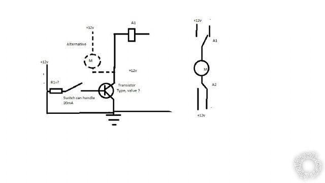 ------------- No reason not to try
Posted By: oldspark
Date Posted: August 11, 2010 at 10:55 AM
Oh geez I know about that culture collision!
There is a federal election looming and those Waussies & Perthians think they are funding the whole country. This might be their go for independence. Forget the centuries of subsidising their economy and under 1 person per square kilometer.
I reckon leave them to themselves; change the old Brisbane line to the WA line, and let our northern neighbours have them. We'll pull out Defenses east of WA, severe the WA OTR radar links, and finally be rid of WA beer. That'll take "Boat People" off our election issues. (For those that don't know, Refugees & Asylum seekers are "illegal immigrants" and everyone (especialy Aussies) know that Orstralia is the destination of choice. Yep, these Ozzies are a clever bunch. Banana Republic isn't it?)
We'll still charge interest on Alan Bond's debt, and take credit for winning the America's Cup.
The 12V shouldn't cause joystick problems - it's more a case of limiting current. And 1mA is enough to drive one transistor to drive a relay; 1uA or 1nA is enough for a FET to do the same.
The circuit would be similar to what you have drawn except the switch (joystick) would be fed from +12V into a resistor to the FET (with another resistor to GND to ensure the FET turns off), and the FET connecting from GND to the relay. Or similar.
I'll check around to see what I think should suit.
Or maybe the other gurus on here have something.
BTW - it was Jens Lekman that was on that TV thingy. I have no idea who he is - at first I thought it was Dennis Lyxzén.
Political bullsh written and unauthorised by OldFart on behalf of other Aus expats.
Posted By: kullakra
Date Posted: August 11, 2010 at 2:16 PM
The fun in this is you are telling me things I should know. I´ve been an electrician for 15 years for gods sake! And now constructing in Inventor 3d CAD. The problem is since I have not used my knowlegde since school it´s gone. Electronics is suprisingly far from working as an constuction electrician. I´m back to school again anyway, in my spare time, and this can come in handy, the next course is automation.
I opened the original module in the seat, the module I like to replace. There are relays on the outputs there too, but it seems like only one for each actuator. They have 8 pins. I will investigate this. Maybe I can use them if they are some kind of double relay with 2 coils?
But the 6 pins can be a double alternating rocker too with one coil. Then the polarisation changing must happen before the relay?
This is strangely interesting. From a practical issue it has moved to being a project to learn from. Maybe I will put the seats in my 1600 touring instead just for fun.
Even I dont know what Jens Lekman looks like so I will check that too.
Political bullsh is a source of laughs to me. Sometimes politicians trip over humor and get suprised themselves.
-------------
No reason not to try
Posted By: howie ll
Date Posted: August 11, 2010 at 5:00 PM
Yes but I watch Wallander and Oldspark should I tell your friend where your family comes from?
-------------
Amateurs assume, don't test and have problems; pros test first. I am not a free install service.
Read the installation manual, do a search here or online for your vehicle wiring before posting.
Posted By: oldspark
Date Posted: August 11, 2010 at 8:40 PM
Howard PLEASE! This is a family site - keep it clean. I'm sure the Swedes of all people know where people come from.
However Swede's not knowing much about Australia - that is a change - that takes me back to when Australia was a small European country near the Alps (they bred dictators) and Sweden was a small neutral European country in the Alps (they were still bordering each other on the last map I saw). Maybe the 40,000 Swedes (per annum?) that toured here (aka Cairns) are long gone?
As long as kullakra isn't like a certain other "experienced" Swede that blames everyone else for being wrong... (And despite his years of experience does some very strange things - I suspect he has more time & money than sense - the negative impacts of a high standard of living LOL!) Now if there was only one-L in kullakra I'd feel safe....
As to Wallander, I think most hereon would agree the original series is best. (Why remake it in English? Isn't that for the yanks?)
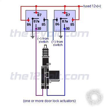
kullakra - if relays are ok, the basic connection is simple....
EG - see 12volt's Relay Diagrams - Door Locks - Actuators / Reverse Polarity - Positive Switch/Trigger... ie:
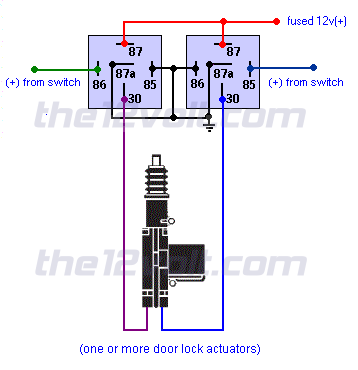
That may be better understood from posts like reverse voltage for boat, especially page 2.
And hotwaterwizard had a few here and there - eg, solid-state (no relays) at reverse 12v motor relays where transistors could be replaced by FETs...
But why not start with two SPDT relays per motor and see how that goes.
The main joystick issue is limiting current to under 20mA which means at least ~700R (R=Ohms) relay-coil resistance.
In practice that means a transistor or FET per contact/relay (and 1 or 2 resistors) and various examples in here (the12volt) can be used.
But is it worth trying the relay connectivity first?
2 SPDT relays that handle the 5A motor current. Why not common 12V 15A or 30A SPDT relays (5 pins - they have both 87 & 87a terminals).
And actuate the relays one at a time - though the motor is supposed to be stopped before reversing direction.
(Having both relays off or both on is not a problem.)
Posted By: kullakra
Date Posted: August 12, 2010 at 4:31 AM
Well I guess you´re not from Australia then, but I don´t need to know that. And Howie: Dont tell if its some kind of secret. I am glad to get help with the seat controls-thats all. No need to make fun of me. And I really dont have more time and money then sense. I missed the fun in Kullakra with one L though?
The relay connections is no problem. This I know. The question is about operating the relays with less current through the joystick. and I have to use small relays to fit under the seat. Not much room there. There will have to be 18 relays to operate 9 motors? With the lumbar support 2 more.
Operating the relays together is no problem I think. The joystick can only close one contact at a time. And the gearbox will stop the motor at once when the button is off. And the motors are with built-in limiters (bimetal?)
So I would appreciate a layout with values and placing of the components regarding resistors, transistors(or MOSFETs) and eventually diodes to make this work. Or point me to another example that may work in the forum. The hotwaterwizard connection nr2 is what I will use but this have to be contolled by the joystick.
Your help is appreciated.
Thank you
-------------
No reason not to try
Posted By: kullakra
Date Posted: August 12, 2010 at 5:02 AM
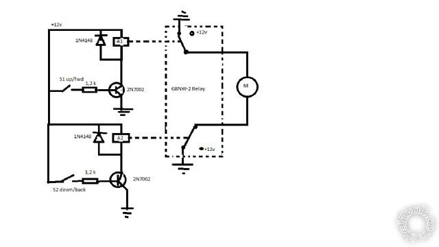
Just found out about the relays: G8NW-2, it is 2-coil relays for automotive use. So I will use them.
-------------
No reason not to try
Posted By: i am an idiot
Date Posted: August 12, 2010 at 8:21 AM
https://www.the12volt.com/installbay/forum_posts.asp?tid=114792&KW=2n6491#556471
The current draw from your switch will be minimal, the diagram says from your 500 MA output. That is for his application. The draw on your switch will be well below your 20MA.
Posted By: kullakra
Date Posted: August 12, 2010 at 8:48 AM
His output is negative. Since I am the idiot here I have to ask: Can I connect +12v on one side of the switch and the other side to B and the switch will work fine?
-------------
No reason not to try
Posted By: howie ll
Date Posted: August 12, 2010 at 11:51 AM
Most certainly not having a go, I don't know you well enough and you've certainly said or done nothing idiotic apart perhaps from starting this project.
The humerous part is that Oldspark's family are part Swedish.
Oldspark, I did mean the original version in Swedish, the US version will naturally be emasculated without the "earthy" language.
-------------
Amateurs assume, don't test and have problems; pros test first. I am not a free install service.
Read the installation manual, do a search here or online for your vehicle wiring before posting.
Posted By: kullakra
Date Posted: August 12, 2010 at 1:15 PM
Surely this can´t be difficult enough to be idiotic? You can´t mean it was idiotic to post the questions? I´m sure a lot of people here can help me. This must be easy for you.
I understand that the answer is out there (in this forum) but I find it difficult to see the connection to my project. I will try harder:)
I belive my family has always been Swedish I but everyone from my grandmother and up is dead.
-------------
No reason not to try
Posted By: howie ll
Date Posted: August 12, 2010 at 1:36 PM
No I meant the number of relays.
-------------
Amateurs assume, don't test and have problems; pros test first. I am not a free install service.
Read the installation manual, do a search here or online for your vehicle wiring before posting.
Posted By: i am an idiot
Date Posted: August 12, 2010 at 1:42 PM
I am sorry, I have no idea why I thought you were switching negative. Radio Shack sells a TIP3055, it will work with positive voltages. Just as you imagined, 12v from switch to B. A 12 Volt power source to C and E will then power terminal 86 of the relay. Ground to terminal 85.
Posted By: oldspark
Date Posted: August 12, 2010 at 8:58 PM
Okay - where's my reply after kullakra's August 12, 2010 at 6:48 PM reply? Don't tell me that other Swede is now deleting my posts as well? (Not you kullakra, I'm referring to someone from Sweden's backside.)
Oh well, here's the modified drawing for ground switching - ie, a grounded joystick.
OOOPS - I just noted a (pedantic) error - by convention, the +12V coil connections should be to #86 and the gnd (less +ve) to #85. I have drawn it to both (ie +12V to LHS relay #86 & RHS relay #85; the +12V should be to #86).
This only matters though if you have spike suppression diodes in the relay, or wired externally....
Posted By: kullakra
Date Posted: August 13, 2010 at 1:37 AM
Now you got me wondering what you wrote in that message..........
I can use ground switching but I will go with the positive to make it easier for myself.
i am an idiot: The tip3055 seems like it has 15 A output? That would mean I can use this in direct connection to the motor? Or am I Wrong?
Here is another drawing I made yesterday. It involves the relays I can use from the original control box. Is the component types ok? (values) Can this work?
Will the current over the switch be 10mA or did I calculate wrong? The coil resistance is 180-225 Ohms. Im I missing any component?
 ------------- No reason not to try
Posted By: oldspark
Date Posted: August 13, 2010 at 5:40 AM
Dang - it happened again... but this time a dropped connection... nearly a bit-bucketed reply. (But I saved to notepad++ before a reboot.)
Now to my former reply. Verbatim. Even with the crap at the end which I was thinking of moving to a PM instead. But why should I bother acting decent of professional?
Besides, others may appreciate the "I'm experienced with over 25 years...." etc which made him correct. I wonder why he deleted his posts though? Other Swedes are not like that!
.....................
PS - I forgot - use 1N4004 (etc) diodes rather than 1N4148 which are signal diodes rather than power diodes.
.....................
LOL! I was thinking why use a transistor... What's this ruddy 2N7000 anyway....
Oh - it's an N-ch mosfet. (Yay!)
But it is only a low current device.
I usually take a one-size fits all approach - namely 60A-70A MOSFETs that can be obtained for ~$2.
They have lower on resistance as well. (2N7002 is ~5 Ohms!)
And being FETs, there is still negligible gate current.
(Unlike transistors - eg, a 2N3055 has a gain of ~20, hence for 10A you need a base (gate) current of 10A/20 = 500mA which is too much for a 20mA joystick. FETs require nA or uA.)
I suggest a resistor from the gate to GND to ensure the FET turns off in case of stray capacitance etc.
And the gate resistor (1.2k shown) can usually be anything - they are usually to protect the supplier of the gate "voltage" (joystick, or (NE555) PWM circuits etc). So assume 20V/20mA = 1k or larger. 1.2k is cool. But could be 10k or 100k etc.
Gate-GND resistors are usually (up to) 1M. It's not critical, but it forms a voltage divider with the Gate resistor ((1.2k).
Make it ~10 (or more) times the values of the gate resistor hence you "drop" les than 1/10th the gate's voltage. (No problem - usually 5V drain voltage (Vgs? or is it Vgd?) is enough for a full turn on, and we have 12V to play with.)
So if Rg = 1.2k, the Rgs should be 12k, or 100k etc.
(If Rg = 10k, then Rgs = 100k or 1M etc.) (If not Rgs, I mean fro the gate to GND for an N-ch FET. I think??)
I like FETs 'cos there are no base-current and "gain" issues.
You can actually connect the FET's gate straight to 12V to turn it on - no resistor is needed - it is a high-impedance input. You can't do that with a transistor!
BTW - I too think +12V switching is easier. Not that P-ch FETs are difficult to come by, but there can be complications. (I've forgotten all that "high-side" switching stuff.)
FYI - re Sweden's backside (I like Göteborg's humör!) - I didn't write anything other than the truth!!
The backside "begged to differ" about my comment/s regarding a series of 3 or 4 LEDs (to be powered from a 555 PWM circuit).
Baksidan was under the impression that resistors were needed to prevent thermal runaway; that a runaway string would "rob current" for other parallel strings; that LEDs would NOT tolerate more than their "rated" 20mA; and that you "have to" put capacitors on PWM outputs to filter the voltage!
I think he finally figured out that he didn't understand circuit analysis, Ohms Law, spec sheets, and the principles of PWM. The datasheet he provided for the 20mA (whatever) LEDs clearly showed those LEDs could tolerate 150mA or thereabout (with appropriate duty cycle!).
He thought I had an attitude problem.... But it was he that later deleted all his incriminating posts. Priceless! (Bad luck for him however - the original now hangs in some Hall Of Fame somewhere.)
And this month's SiliconChip magazine features a project with a LED display using all the features I described to him - resistorless 2V LEDs off a higher supply (5V?) with peak currents of ~100mA instead of their "rated" 20mA. FIGJAM!
I wonder if he still adds capacitors to PWM outputs?
[ FYI - PWM - Pulse Width Modulation - a method of "chopping" the current to a circuit hence enabling dimming or speed control... essentially varying the power but keeping the same operational voltage. Used for LEDs because changing the voltage doesn't work well - instead you keep its voltage constant but turn it off quickly at different "duty cycles" to vary the power (current) from 0% to 100%. Works for fluoro lights too. ]
Posted By: i am an idiot
Date Posted: August 13, 2010 at 5:44 AM
The transistor would probably handle the current of your motors. But the transostor will not be able to switch from ground when at rest to positive to move the motor when needed. You have to use the 2 relays per motor. The coil of a Bosch/Tyco relay draws 160MA. you could use a smaller transistor, I like to overengineer. It reduces failures.
Posted By: kullakra
Date Posted: August 13, 2010 at 7:18 AM
Now I´ve read the two last answers a few times and I understand it like this:
I can do like this but change the 1N4148 to 1N4004 and connect a resistor 100k from gate to gnd to make the 2N7002 turn off?
And it´s ok with the relay(coil res 180 Ohm)? It´s a double coil relay so it´s perfect.
The 2N7002 I can buy for like 2 spänn:)
PS I live on the downside maybe? It looks like a plot is hiding in this forum well suited for Wallander! I guess turnips is some kind of ogräs? The Wallander movies has been like that for some years I think. Theres not enough time to see them all. But do you think Krister or Rolf is best as Wallander?
-------------
No reason not to try
Posted By: oldspark
Date Posted: August 13, 2010 at 10:50 AM
How's this.....
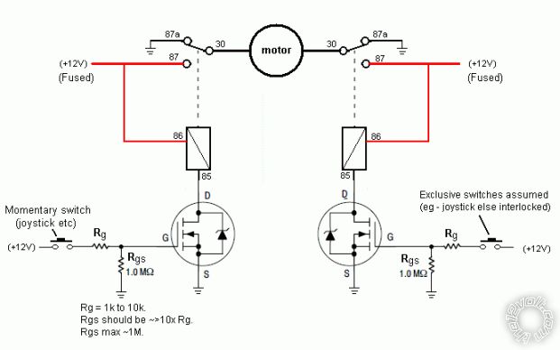
I haven't shown the diodes.... I'm used to MOSFETs including a "freewheeling" diode (as shown in its circuit symbol), though not all include it. But is is best putting a (reverse biased) diode across the relay coil. (For the FET and other sensitive circuitry...)
You can use an NPN transistor instead of the N-channel (MOS)FET - terminal GDS become BCE, and the resistor values will have to change. And you need a suitable transistor gain etc.
Not sure what is meant by the "dual coil" relays - or is that just two relays in one housing? (Great until one fails.)
I think the 2N7002 should be ok (500mA?).
As I said, I'd tend to use MJT3055 (the FET equivalent of the 3055 transistor; handles ~15-20A) or even bigger ones. The there is little question about current capability, and if I add another 2 FETs (4 per motor), I can get rid of the relay.
A swede is a type of vegetable - similar to a turnip. (But I've never eaten the vegetable. Some Swedes taste like mice though....)
And that Swede (he probably lives in Fitja) is on another forum. I don't think his ego and insecurity would last here.
Alas no job for Wallander.
As to Krister of Rolf.... I only remember the later character, though I saw the original in "After the Wedding" (Efter Brödloppet??)
Ah - that's Rolf Lassgård. He's great! But Krister is superb.
It's just a shame about the daughter.....
Posted By: kullakra
Date Posted: August 13, 2010 at 11:21 AM
Now I have something to test. Thank you very much! I will build one of these to try it out and tell how it went.
-------------
No reason not to try
Posted By: dualsport
Date Posted: August 17, 2010 at 11:14 PM
You sure you want to use 2N7002 rather than a 2N7000?
The 2N7002 is quite tiny, and unless you have real space constraints, you might find the 2N7000 much easier to work with.
Somewhere the original suggestion of 2N7000 got switched over.
I used BS170's with a bit better specs, but have a bagful of the 2N7000's because they were a bit less lower cost and basically equivalent.
Posted By: oldspark
Date Posted: August 18, 2010 at 12:35 AM
I'd go big.
Why not get 20A-80A capacity FETs instead of 0.5A when the prices are so similar?
As I wrote (somewhere), I get 60A-80A MOSFETs for about $2 each and use them for everything.
Posted By: dualsport
Date Posted: August 18, 2010 at 7:54 AM
Price and size mainly. Overkill is fine, but if it's just being used to drive a relay, 10 cents vs. 2000 cents, and the smaller size makes them easier to stash away.
If you're stocking up you could always just get stockpile an assortment big and small, and use whatever's needed.
Posted By: kullakra
Date Posted: August 19, 2010 at 3:08 AM
As I need about 40 transistors or MOSFET:s and 40 diodes the cost is a factor of course. I just tried a BC546B that was lying around at home and it does the work so even if I would prefer MOSFETS I will use something smaller if it works.
Size is also important.
I see your point though Oldspark.
I will make a working model and tell how it went.
-------------
No reason not to try
Posted By: oldspark
Date Posted: August 19, 2010 at 3:46 AM
If you already have the relays and want to keep them, cool. Then 546s or whatever works.
But in place of relays.....
|