2 3 seconds to trigger relay
Printed From: the12volt.com
Forum Name: Relays
Forum Discription: Relay Diagrams, SPDT Relays, SPST Relays, DPDT Relays, Latching Relays, etc.
URL: https://www.the12volt.com/installbay/forum_posts.asp?tid=125630
Printed Date: May 09, 2026 at 10:18 AM
Topic: 2 3 seconds to trigger relay
Posted By: cmorales
Subject: 2 3 seconds to trigger relay
Date Posted: January 12, 2011 at 3:05 PM
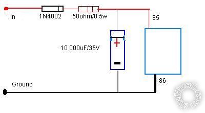
I been searching for a way to trigger a relay ONLY if I press a switch longer than 2 or 3 seconds and only thing I could find is this old tread.
Will this work or is there a better simpler way?
Thanks.
Replies:
Posted By: i am an idiot
Date Posted: January 12, 2011 at 8:43 PM
That is pretty much a failsafe way to do it.
Posted By: cmorales
Date Posted: January 13, 2011 at 9:41 AM
Thanks.
I´m trying to prevent opening the trunk by mistake, the switch is too accesible...
Can I put two 4700uF capacitors in series to get 9400uF?
Posted By: cmorales
Date Posted: January 13, 2011 at 9:48 AM
Found it... the capacitors need to be in parallel to add capacitances.
Thanks
Posted By: cmorales
Date Posted: January 13, 2011 at 10:17 PM
Well. It didn't worked. Could it be because I used two 4700 uM capacitors in parallel?
Posted By: i am an idiot
Date Posted: January 14, 2011 at 10:05 AM
The only thing that would keep this from working is the direction of or the placement of the diode. The drawing has the diode in the positive leg. If the diode is in the negative leg, you must turn it around.
Posted By: cmorales
Date Posted: January 14, 2011 at 11:00 AM
connected everything as the diagram. only thing different is the capacitor, I used two 4700uF/25v capacitors in parallel. The thing was that the relay activated instantly and not after 2 secs.
Posted By: cmorales
Date Posted: January 14, 2011 at 11:23 AM
Here´s a better description of what I´m trying to solve...
...In my car (12v, negative earth) I have a boot opening switch (momentary) that opens the boot by triggering a solenoid. All well and good but they situated it right next to the power windows. The number of times I have just brushed it whilst opening the window is getting beyond a joke and quite embarrassing at traffic lights.
What I would like to do is to have to hold the switch down for 2 or 3 seconds before it passes the voltage to the existing relay that feeds the boot solenoid. If the switch is pressed and released then the timer is reset (obviously don't want accidental presses building up)...
Thanks
Posted By: cmorales
Date Posted: January 14, 2011 at 1:51 PM
What if put the resistor between the capacitor and the relay?
The relay is a 12v/30A automotive relay. Does that makes a difference?
Posted By: i am an idiot
Date Posted: January 14, 2011 at 8:40 PM
The resistor has to be exactly where it is in the diagram. Are you sure you have a 50 ohm resistor, and 4700 mic capacitors.
Posted By: dualsport
Date Posted: January 15, 2011 at 2:15 PM
It'd be better if you used a transistor driver instead of directly driving it like that.
The problem is that the 50 ohm resistor charges up the capacitor too quickly for your purposes. A larger resistor and/or capacitor would extennd the time delay, but- you have a limit on how large a resistor you can use because you're trying to drive the relay through it, and a limit on the capacitor because it'd get ridiculously large.
I'm sure there's post from the past for this purpose with details, if you have any interest in using some electronic bits, I'll look for it-
Posted By: dualsport
Date Posted: January 15, 2011 at 2:26 PM
The mention of electronics and solid state scares off a lot of guys, but this is actually pretty simplistic, and actually would be cheaper than trying to buy humongus caps.

If you go with humongus, you might note that the relay will remain on for a time after you try to release it also, if that's any concern.
With the solid state driver, you'll be able to drive it with alarm drive outputs without worry about overloading them from the extra drive current.
Posted By: cmorales
Date Posted: January 16, 2011 at 12:33 AM
Can I use that circuit with a negative pulse for input?
Posted By: cmorales
Date Posted: January 16, 2011 at 7:33 AM
I am an idiot: I just checked the capacitors I'm using and they are 470uF.
Dualsport: yeah, humongus is an acurate description for a capacitor of that capacity. It's bigger than the relay I'm using!
Thanks to you both.
Now: can I use a switch negative and constant 12v on that circuit. I suppose that changing the values of R1 and C1 will change the delay duration, right?
Will the relay once activated release as soon as the input signal is no longer present?
Thanks
Posted By: dualsport
Date Posted: January 16, 2011 at 10:14 AM

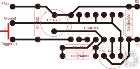
This should allow you to trigger with your neg trigger.
If your input trigger is already (+)/(-) signal you can delete some of the stuff in the front end.
It should delay the onset of the relay being energized and turn it back off as soon as you release the trigger.
The other benefit of using a solid state drive instead of directly driving is that the relay turns on and off faster, which is better for the relay contacts. When you have a slow drive such as the capacitor direct drive where it charges slowly to energize the relay, the relay contacts go through a period where they're high resistance for a longer period of time.
If it's just a light duty load then this isn't a big deal but if you're switching high current loads, it degrades the relay contacts more than if they switch open and closed quickly as they were designed to do. A relay rating of 30A is based on a fast switching time.
Posted By: cmorales
Date Posted: January 17, 2011 at 11:33 AM
Thanks dualsport... Will try to buy the parts tomorrow...
Did you changed the last circuit and removed a couple of diodes on the left?
Posted By: cmorales
Date Posted: January 17, 2011 at 12:44 PM
How's this?
Posted By: dualsport
Date Posted: January 17, 2011 at 6:50 PM
cmorales wrote:
Thanks dualsport... Will try to buy the parts tomorrow...
Did you changed the last circuit and removed a couple of diodes on the left?
Yes, they're not really necessary because they're built into the IC, so you can do without them to simplify-
Posted By: dualsport
Date Posted: January 17, 2011 at 6:57 PM
cmorales wrote:
How's this?
I'm impressed- 
The drain and source on the transistor is reversed (that is, your outline and pin definitions are correct, but the wiring is swapped- pin 1 is Drain, pin 2 is Gate, pin 3 is Source), but if you just plug it in 180 degrees from the outline shown, it should be fine (or use a 2N7000, which has the opposite pins )-
Also, be sure to observe polarity on the diodes and caps, since they're not marked on there.
p.s. Check mouser.com for the parts if you have any problems finding them at a reasonable price.
|
