momentary to latched woes.
Printed From: the12volt.com
Forum Name: Relays
Forum Discription: Relay Diagrams, SPDT Relays, SPST Relays, DPDT Relays, Latching Relays, etc.
URL: https://www.the12volt.com/installbay/forum_posts.asp?tid=128722
Printed Date: April 18, 2026 at 7:18 PM
Topic: momentary to latched woes.
Posted By: vortecyota
Subject: momentary to latched woes.
Date Posted: October 04, 2011 at 7:24 AM
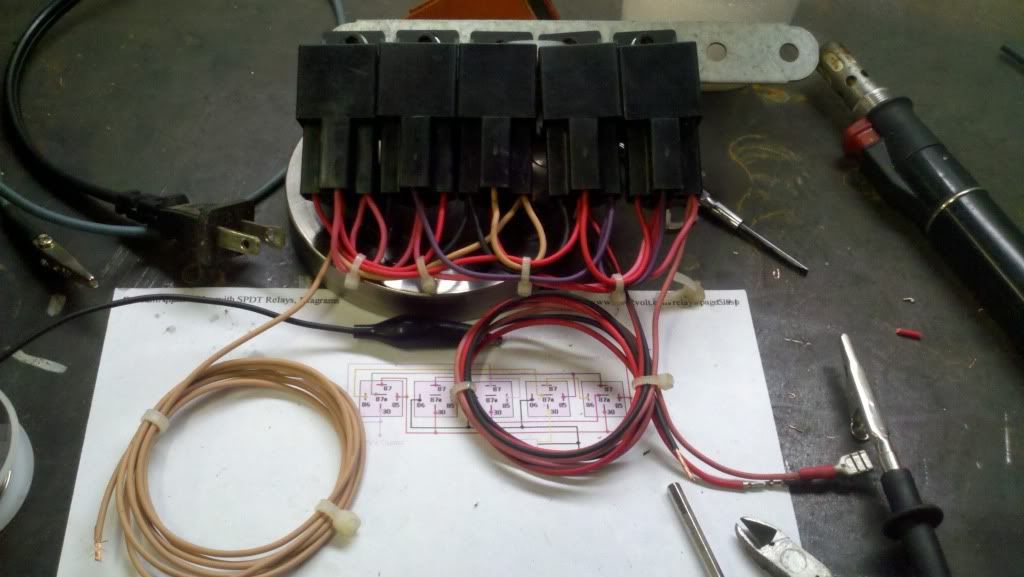
Hey guys. I built a 5 SPDT relay configuration following the "momentary pulse latched on/off with no diodes" diagram on the main page. I need to incorporate this into my vehicle before towing my camper out of state later this month, but have not made it past bench testing.
It IS working, though not as well as I would like. When I power the system up and pulse the input to Gnd, the output latches ON. However, when I pulse the input to Gnd again, it will only latch the output OFF if I pulse it extremely fast. If held for any longer than a fraction of a second, the system will click but stay on.
Is there a remedy to this or is issue inherant to the design? Thanks guys!
Replies:
Posted By: vortecyota
Date Posted: October 04, 2011 at 9:03 AM
Update: I have done some more bench testing this Am. Now I am using the momentary switch that I would like to use in the vehicle instead of just touching the input to ground manually.
It seems to work much better now. It wont latch OFF maybe 1 out of 20 or so switch pulses.
Now I would like to reconfigure this harness so that the input needs 12v instead of Gnd. Unfurtunately, I am just not sharp enough to do so. Untill yesterday, I had figured out how to implement two relays in order to perform a certain function, but had no idea about the many possibilities using 3+ relays. I fully understand a single SPDT relay and how it functions. Add three or more and my head starts to spin.
Any gurus have time to help me reconfigure for 12v input without adding a sixth relay?
Posted By: vortecyota
Date Posted: October 06, 2011 at 7:21 PM
Wow. If im an idiot wasn't already a username here, I would use it :( . Just swap 12v and Gnd and now it needs a 12v input. Sorry im a moron. Works how I need it to now.
Posted By: vortecyota
Date Posted: October 06, 2011 at 10:03 PM
Can't seem to win here. The purpose of this latching relay setup is to use the output to switch an additional SPDT relay between two circuits. The NC contacts will connect my PCM to my overdrive solenoid(2005 Dodge Cummins) for normal operation. When this additional relay is energized, the NO contacts will connect the PCM to a dummy circuit(~46ohms) with 12v on the other side just like the solenoid does in the trans.
The idea here is to be able to inhibit overdrive while towing without setting a DTC. I have tested the rough version of these relays including the dummy circuit and it works flawlessly with no dtcs. Remove the dummy resistor circuit and a dtc sets every time.
The problem is that for my momentary switch with built ion LED to work, I need the input signal to need 12v instead of Gnd and the output to be Gnd instead of 12v.
I thought I had it when I reversed the power and gnd to the relays. It did make the input need 12v. However, that's when two problems surfaced. The output was still 12v. Also when I added the additional relay, after energized one time, the setup would not unlatch.
Am I being too descriptive? Not enough? I really need some help.
Posted By: oldspark
Date Posted: October 06, 2011 at 10:59 PM
I don't understand the reason for the latcher, but alternatives are easy. However these can involve anything from a diode or 2 (with one relay) or IC gates or flip-flops and a relay.
I have never been a fan of using many relays for a simple function. EG - a 2-button latcher (on & off) is merely 2 diodes and an SPST relay; a single-button (toggle) latcher is 2 inverters (gates; else a flip-flop) and an SPST relay. I prefer that "complexity" to needing the extra 4 relays.
Posted By: vortecyota
Date Posted: October 08, 2011 at 10:00 PM
Thank Oldspark. I guess what I should be asking is what is the simplest way to use an existing momentary 12v output switch to "latch" an SPDT relay. One push latches the relay on. Another push latches it off.
My switch is existing and must be used. I need the relay to connect 1 PCM controlled ground circuit to my overdrive solenoid( 87a/30 ). With one push of my momentary switch, I need 30( PCM ground signal ) to be connected to a "dummy" overdrive solenoid (87/30)( keep from setting a trouble code ). Then connect 87a/30 again with another push of the switch and so on.
I have tested this setup and it works flawlessly, except it takes 7 relays to make it happen and I would like to simplify it.
In case you are wondering, I have a 2005 Dodge Cummins diesel. The only year without an OD cancel feature.
Posted By: oldspark
Date Posted: October 09, 2011 at 7:19 AM
The toggle circuit I like is
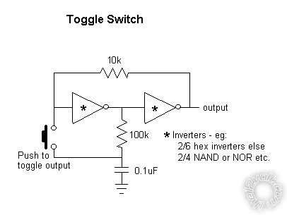
as per latched on/off momentary w/ brake kill.
It should be possible to do the same with transistors or FETs...
A (dual) flip-flop chip can also be used - the easiest may be to wire an SR flip-flop as Toggle type as per Converting Flip-Flop Input Types .
The selected devices need to source/sink the relay coil current, else a buffer added that can (eg, transistor or FET).
Posted By: alencarfr
Date Posted: March 15, 2012 at 11:03 AM
Hi Dear,
I also built the circuit but for me it don´t work! Before read your post I was condering the circuit has some error in the project. But now you say yours is working.
Any tip you could send to me !?
Thanks
Alencar
Posted By: oldspark
Date Posted: March 19, 2012 at 5:16 AM
From latched on/off momentary w/ brake kill...
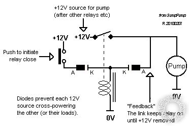
The diodes are only there to prevent power feeding thru the coil and switch circuit.
The next "physical" diagram shows the above but with the NC feedback switch - ie, push to break feed back hence unlatching the SPST relay - assuming the "push to latch" switch is off.
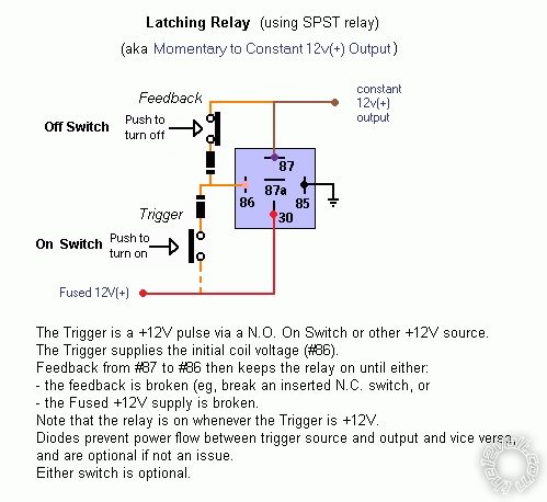
The above is simpler if 2 switches can be used.
I have used the inverter-gate toggle circuit, but not for relays. Relay coils would probably require a spike-suppression diode, and bear in mind that the inverters or gates themselves may not be powerful enough to source +12V or sink (GND) a relay coil, hence a transistor etc must be added.
|