On/Off Latching Circuit with 2 Relays?
Printed From: the12volt.com
Forum Name: Relays
Forum Discription: Relay Diagrams, SPDT Relays, SPST Relays, DPDT Relays, Latching Relays, etc.
URL: https://www.the12volt.com/installbay/forum_posts.asp?tid=138488
Printed Date: May 14, 2026 at 10:11 AM
Topic: On/Off Latching Circuit with 2 Relays?
Posted By: brconk
Subject: On/Off Latching Circuit with 2 Relays?
Date Posted: February 14, 2015 at 12:21 AM
I'm teaching a class on basic electrical... I was gift this lab sheet and cannot figure out the third part. Only using two micro relays, SPST switch, and a push button??? Is this possible?? If so please give me a schematic
First part:
Using a circuit board, wire a light through a SPST switch and a flasher.
When the switch is closed, the light should light and then flash.
When the switch is turned open, the light should go dark.
Second part:
Wire the light, the SPST switch, the push button and the flasher through a relay so that when the switch is closed and the button is pushed, the relay is energized and latched, and the latch is then broken by the SPST switch.
Third part:
With a second relay, create a circuit so that when the pushbutton is pressed a second time, the latch on the first relay breaks.
(hints: the latch circuit will originate through the second relay, the second relay will energize when the SPST switch is closed, and the polarity of the push button will change)
-------------
Brad R Conklin
Replies:
Posted By: oldspark
Date Posted: February 14, 2015 at 3:35 AM
Lucky I have such a good attitude to teachers. I must have had the best - like the digital teacher that used 2 down counters to convert binary to decimal in a CPU; another that thought an LM317 adjustable voltage regulator "must've had an adjustment screw" and laughed at us for having difficulties designing a 2-transistor amplifier but then came running after the Dean received a petition from a certain student [guess who!](he also used to disconnect his UK domestic power from earth/ground!); the guys that penalised me for not agreeing with others after proving Prac answers had been wrong for at least 4 years; the Dean that had us draw excessive graphs from tabulated appendix data so that we "got the feel for the (parameter) relationships" when those tabulations were taken from the texted formula as opposed to "real" measurements...
Luckily there were others that educated us - apart from ourselves of course.
You should be able to find solutions on the internet. That's how many students do it.
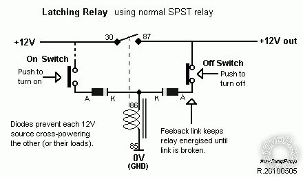
Of course there is a latching circuit that uses one SPST relay and 2 switches (for on & off)...
Posted By: brconk
Date Posted: February 14, 2015 at 6:56 AM
I've searched the internet with no avail! I'm by no means a electrical engineer... Just a diesel technician teaching part time. I don't know why but this circuit is hauting me.
Is it possible to take two 5pin relays, a spst switch, and a momentary pushbutton to build part three???
Thanks for the help
-------------
Brad R Conklin
Posted By: oldspark
Date Posted: February 15, 2015 at 4:39 AM
My apologies - you are a REAL teacher. Actually my tertiary mech engineering teachers/lecturers were very real - I had no complaints with them. (You may have noticed my examples were all electronical & electrical.)
So yeah, #1 is easy, & #2 is essentially my oft posted diagram...
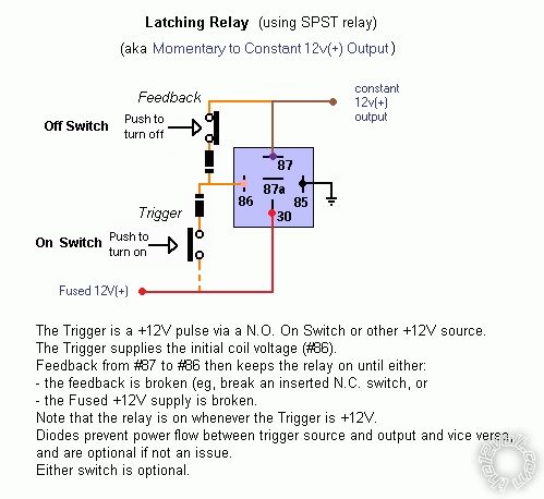
... with diodes omitted and where the push to turn off is the normally closed SPST switch.
FYI - whilst IMO the latching circuit shown is simple and easy, I'm amazed at the number of published equivalent circuits that use additional electronics. When I needed that circuit I knew intuitively that it could be done but I lazily resorted to web & magazine searches. One popular local magazine (SiliconChip) had 3 such circuits all with the unnecessary extra circuitry (ironically (IMO) all 3 contributors got paid for their suggestions!).
As to #3, I reckon it can be done tho it's usually done with more relays else multiple contact relays (DPDT etc) else with extra components. In fact I'm certain I came up with a circuit...
However my mind is now lazier than my attitude once was - maybe some other brilliant minds hereon can come up with the solution? I'm still recovering from a long day at the beach.
Incidentally, my best learning as well as teaching has often come from group brainstorming - ie, where teachers claim not to know the solution so they work it out with the victims students. IMO such learning experiences are far more valuable - ie, the methodology of how to solve or research rather than the solution itself. Besides, the joy of having some students forever ponder whether the teacher merely pretended not to know the answer is a joy to behold (yeah, I'm sadistic  ).
Posted By: oldspark
Date Posted: February 17, 2015 at 1:43 AM
I'll bow out of this. I've had a few goes but can't nail it using two SPDT relays and a momentary push button (N.O. SPST).
Of course the question's originator should have a solution & IMO that should be available.
Chances are the solution - if any - will come to me passively. (Hence in part why I'm formally bailing out.) But otherwise, please post the solution - or PM me if confidentiality is an issue. No doubt I'll kick myself when I see it, else perhaps see its unstated parameters.
Posted By: mpegandy
Date Posted: February 18, 2015 at 8:33 PM
Hi oldspark,
May I ask a question?
What schematic program are you using to draw up those great drawings?
Thanks for your time,
Cheers!
~ mpegandy
-------------
"The greatest oak was once a little nut who held its ground..."
Posted By: oldspark
Date Posted: February 18, 2015 at 11:45 PM
I used Microsoft's Draw package that I had with Windoze 2000 until my Windoze 7 upgrade a year or 2 ago.
(Hence why I no longer initiate drawings - I don't find MS Paint as convenient, nor other CAD packages that I have used.)
Actually I thought my posted pic above included...
Stupid me - I didn't realise they were 2 separate files!
But they are from capacitor value for latching relay? as well as other websites (typically the12volt & mp3car.com).
And more FYI - I never draw wiring type diagrams as per my first pic but always circuit type diagrams as per my second pic.
Those absolutes were broken in a few cases because (1) the12volt had such great relay (base) drawings & (2) they are so popular here and elsewhere, but mainly because of (3) I allowed myself to succumb to certain audience desires.
Unfortunately such audiences may have problems using non mini-DIN relays (eg, the newer micro-DIN as well as any other relay) whereas my circuits are universal - the user just needs to translate the pins to the relay at hand.
[And mini-DINs almost always provide a schematic on their case; hence why I never leaned the 85, 86, 30 & 87 DIN convention, and I never trusted 87a labels as sometimes these were a second 87 terminal! Besides which DIN relay terminal numbering (should) vary with the application even if the relay itself doesn't (electrically/physically speaking).]
|