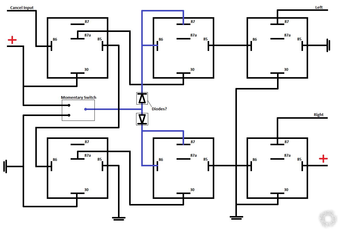
Hello all, I am in a bind with wiring up some indicators. The input is singular and either +ve or -ve depending on direction, it is also a momentary pulse (with a second input to cancel).The indicators themselves are then a separate -ve feed circuit. The input cannot be altered so I have put some significant time in to figure out how to make this work with basic 12v circuitry.
The attached file shows my best effort so far, in theory allowing either the +ve or -ve voltage of the input will activate either the top or bottom bank of relays and be self sustaining until cleared by the second input (C). I am confident in the operation of this but I then realised the outputs would simply create a circuit together (thus activating both lights) so I hastily added in diodes but am not confident this would work. Not sure where to go from here, I may have over complicated it, or it may be impossible. I would appreciate some advice! Alternately advice on a component / circuitry that could do the job instead, simplest solution always best.
Ideally either input would cancel the other, but not essential.
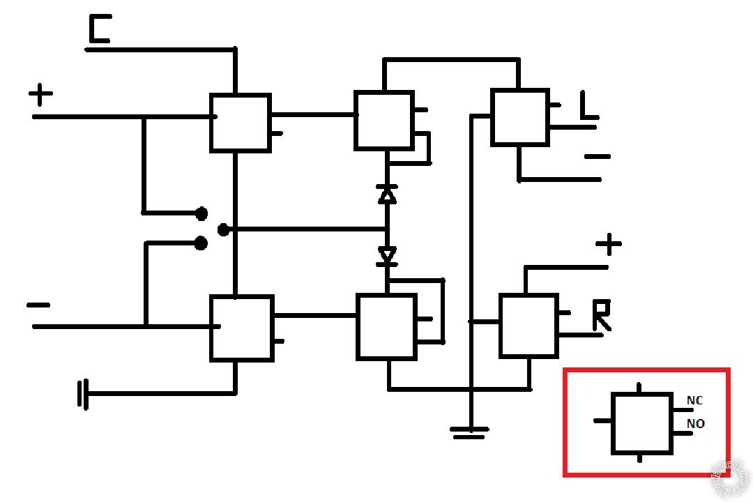
redraw with your relays looking like this
85 and 86 = coil of the relay.
30 = common
87A = N.C.
87 = N.O.
Okay, I shall do. As drawn the relays are (reading clockwise from 12) 85 / 87A / 87 / 86 / 30. New to this so shall try and get a redrawn diagram up asap.
Hard to get it all on screen of phone. I will be able to look at it on a PC tomorrow. The 1 thing I did notice is you have the coils of a couple relays wired in series. This will not work.
Yes this is the problem I need help with! Was hoping for either a solution to this, an improved design or a logic board etc recommendation that could do the job.
https://www.the12volt.com/relays/relaydiagram69.html
This should work for half of your project. Searching for the positive input for the other half
You will have to use a double pole switch to cancel.
This is for the positive halfIf you need it to cancel one when you activate the other we can do that with 2 additional relays. A relay wired to the output of the switch, the output of that relay paralleled with the cancel switch.