Hey guys I bought all the parts I need for a compustar/idata link remote start system. Does anyone have the wire colors and locations? Also need some tips for dealing with the A pillar airbags and lower dash airbag after leaving the battery disconnected for 10 to 15 minutes. Also can anyone tell me if this is a high current or low current install? The DC3 brain I bought apparently needs the high current harness bought separately if that's required. I don't have electric door locks so I'm not interested in an alarm just the remote start function. Also my car is just a regular key nothing fancy.
Thanks
2013 through 2016 are the same.
https://www.the12volt.com/installbay/forum_posts.asp?tid=136382-------------
~wirewise~
Verify all wiring with your meter before making any connections!
Since the 2013 through 2016 are the same I should be able to use a t harness from Idata although it only says it's compatible with 2016 and up. But if the wiring is the same why would it list it as incompatible?
So I'm getting conflicting results for wiring diagrams on this car I created an idatalink account and downloaded their wiring diagram and this is what their guide says. Basically everything connects to the BCM and that's basically it. When I flashed my module it said the high current harness was required but in the guide, the high current wires are greyed out :errr:
Here's the idatalink pdf so someone can take a look:
https://drive.google.com/file/d/1OpRS2ACA2IBWH-AVMFPsGT7nAa8rNhPr/view?usp=sharing
I would follow the install guide. The ignition wires specified at the BCM are thin and low current.
-------------
Soldering is fun!
So I'm going to need the high current harness then too. Why would first tech/idata not specify the ignition ones in the guide? The m1 socket for high current is greyed out. Do I disregard the ignition stuff in the low current harness and just swap the connections for the thick wires? I'll have to check if my car even has thick ignition wires. The wires it wants connected to the bcm in the low current are thin as well as the harness that came with the brain are thin.
Why? The High Current Ignition connector is greyed out and not used.
The Install guide only shows the vehicles ignition wires connected to
the M4 connector. Follow the guide, exactly. They left nothing out.
On some guides for other applications they have a Notation that goes :
STANDARD 12 VOLT, GROUND AND IGNITION SWITCH CONNECTIONS ARE STILL REQUIRED FROM THE REMOTE STARTER.
The GM7 guide does not have this Note. Remember that the DC3 unit is
a R/S and bypass combined in one unit and designed for both high and
low current vehicle applications.
-------------
Soldering is fun!
No, I was just trying to ask a question to clarify that because that's what I thought as well. I didn't think I needed the high current harness looking at this guide. So my application doesn't need a high current harness basically. I'm just trying to get clarification on this from somebody that knows more than this than I do because my last car needed a high current harness and I used a Viper remote start, not an idata kit. Also do I need to drill a hole for the ground wire in something metal on the car or is there someplace that I can ground the DC3 brain to without having to drill a hole any ideas on what I could use for a ground if I have to drill a hole I will but I'd rather not. Also one other question. The guide says to cut the green/white wire at the BCM that's for immobilizer data and attach the white/black wire to it for the immobilizer data vehicle side (DC3-M5 socket) wire on the DC3 brain and then connect the other side of the cut wire at the BCM to the white/red wire to the immobilizer data connector side. When the guide specifies vehicle side they're talking about the wire coming out of the BCM and when they specify the connector side they mean that same wire except since ill be cutting it they want me to connect to the side of the wire that goes away from the BCM to the connector. Correct? That's how I'm interpreting that. I wanted to make sure my interpretation of that was correct.
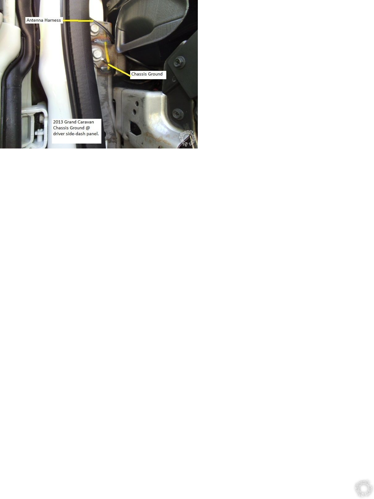
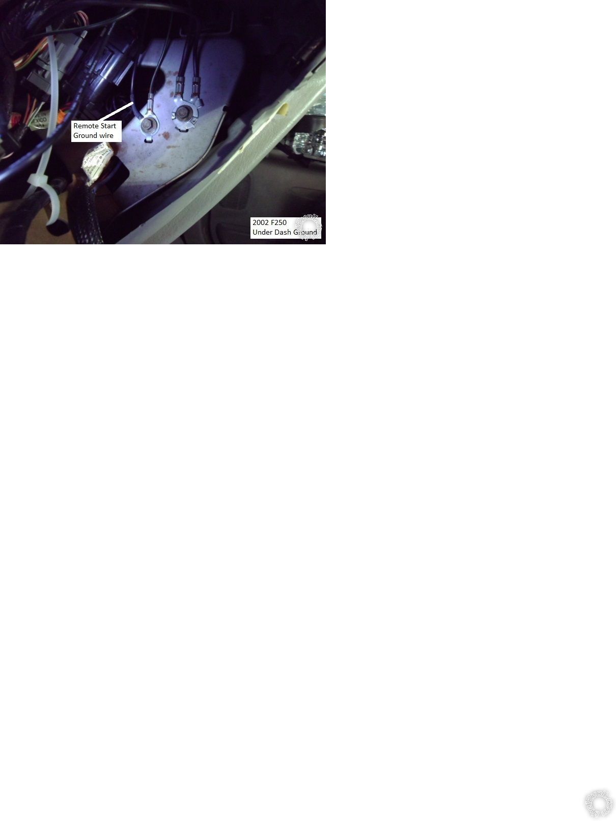
For the R/S Chassis Ground connection you want a very "solid" ground. Obviously the best
choice would be with a soldered on terminal lug connected to the (-) battery terminal. That
is typically overkill. If you look around for a convenient location under the dash, near
where the R/S unit will be placed, you can usually find a Factory ground point where
several factory wires are bolted to the frame of the vehicle. You could use that connection
point with a soldered on terminal lug on the R/S ground wire. Basically any solid frame
location will work, I try not to drill holes in the customers cars but there are times
when it's necessary. Usually there is a shiny 3' diameter pipe under the dash across the
vehicle that is a solid ground point. You could drill a holes in this pipe and then use a
self-tapping screw to secure the R/S ground wire ( with a soldered on terminal lug ).
Last choice is to find a convenient location in the firewall or kick panel, use a wire
brush to remove the paint and then a self-tapping screw through the soldered on terminal
lug of the R/S's ground wire. Just ensure there is nothing on the other side of the metal
panel that the self-tapping screw will hit. Here are some ground location photos :
For the cut Green/White Immobilizer Data wire, just follow the guide. You're over-thinking
this install. The "vehicle side" and the "connector side" are exactly what they mean. On
the Install Diagram, if you drew in a Green/White wire from Pin 2 of the illustrated
connector, through the "IMMOBILIZER (DATA) GREEN/WHITE OR GREEN/PURPLE- 02" description
to the cut wire diagram, that is exactly how you want to make the connections. The DC3's
Green and White/Red wires get soldered on to the cut Green/White wire going to the
BCM Green connector. The DC3's White/Black wire gets soldered on to the side of the
cut Green/White wire going somewhere into the vehicle ( sometimes called the "away side").
Additionally, I always join those two DC3 immobilizer "connector side" wires near the
DC3 and just continue one wire to the cut wire connection point. Makes things neater
and electrically / logically, it's the same.
-------------
Soldering is fun!