Hello,
I was looking through the forum and found a circuit that fits my needs almost exactly. I was wondering if it would be possible to adapt this circuit to revert to the off state whenever the 12v+ is disconnected, rather than staying in the previous state when power is cycled. I would really love to only use the parts shown in the circuit, only varying quantities, but if you have any thoughts that would work just as easily I'm all ears! Thanks!
First thing, whenever that circuit is powered, it will consume the relay coil current - ie, either thru the RHS relay coil else its LHS equivalent resistance R1. That's fine if using a switched source (IGN, ACC, etc) but will drain the battery if hot/constant +12V. However you mention removing the +12V so I assume it is switched.
PORs (Power-On Resets) are usually achieved using a cap - eg from the base of the RHS transistor (2N2222 input from the LHS 2.7k resistor) to GND plus a means of discharging it when power is turned off - eg, a parallel bleed resistor or maybe a diode to 87. When the circuit is powered, the discharged cap will be at 0V (GND) thus keeping the RHS transistor (Q2?) off and hence turning on the LHS. But suitable component sizing is required (eg, cap bleed resistance (much) bigger than 2.7k & the cap (much) lower than 22uF) and maybe a series resistor between the LHS 22uF & 2.7k and the RHS Q2 base & POR cap...
There may be suitable circuits in webland else it's worth checking with HotWaterWizard - I may be wrong or have missed the obvious solution. And the POR may need a minimum off time to cause reset - ie ~RC seconds where if the bleed R with C method is used.
If a 2 button on & off is okay, see
here for a "no circuit" (mere relay) method - the diodes are only required if load current passing thru the switch(es) may be a problem.
And it resets immediately if +12V is removed (assuming a non-capacitive load).
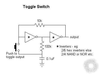
For single button flip-flops or toggles I like the following inverter circuit:
... from
here.
Using inverters may require an output 3rd inverter for the RC POR tho NAND & NOR type circuits (where both inputs are joined to make an
inverter) might only require the 2
inverters (the first NAND/NOR input is disconnected and connected to the grounded RC POR addition).
Otherwise I usually suggest an expandable/configurable
divide by n counter using the CD4017 with its standby current of under 100uA tho that needs limiting to 15V and the POR.
The IC/chip circuits may require power filtering & limiting to 15V etc and enough output buffering to drive a relay, but I offer them as a low current or maybe a simpler
single button option.
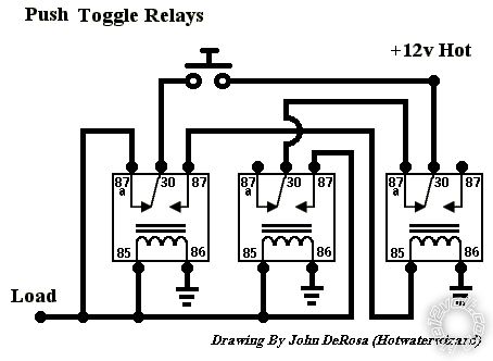
Here we go Peter, depending on current requirements, how about a simple latching relay.
-------------
Amateurs assume, don't test and have problems; pros test first. I am not a free install service.
Read the installation manual, do a search here or online for your vehicle wiring before posting.
Agreed. But I never find the appropriate links. (I seem to find the signal inversion or 2 terminal latchers - not the simple single button single power (toggle) types. I guess there's always Google...)
How about this one?
-------------
John DeRosa (Hotwaterwizard)
Stockton California
When in doubt, try it out !