


trying to turn off sub using switch


Posted: January 13, 2013 at 6:29 PM / IP Logged
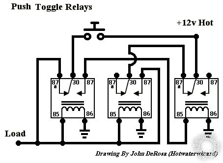 I've tried building this circuit but somehow I failed (maybe used the wrong relays?) and the button still acts as a momentary open one. And also, if I understand this setup correctly it will toggle the sub on upon the first press, and I'd like it to be on standard, and off after pressing the button.
The button I'm using is wired as follows:
I've tried building this circuit but somehow I failed (maybe used the wrong relays?) and the button still acts as a momentary open one. And also, if I understand this setup correctly it will toggle the sub on upon the first press, and I'd like it to be on standard, and off after pressing the button.
The button I'm using is wired as follows:
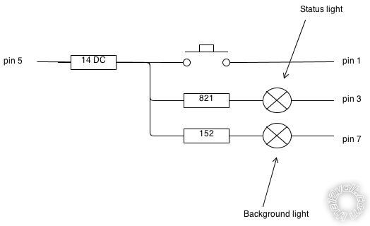 I created this scheme myself and I don't have any background in electronics so sorry if it's not correct!
So in short I'm looking for:
A circuit that will break the remote wire connection upon a button press. If the button is pressed again it would be cool if it were to re-enable the sub, but this is not a necessity.
I'd like to keep the background light on as long as there is a current on the remote wire coming from the radio and the status light must be on whenever the connection is closed and the sub is on.
Thanks!
I created this scheme myself and I don't have any background in electronics so sorry if it's not correct!
So in short I'm looking for:
A circuit that will break the remote wire connection upon a button press. If the button is pressed again it would be cool if it were to re-enable the sub, but this is not a necessity.
I'd like to keep the background light on as long as there is a current on the remote wire coming from the radio and the status light must be on whenever the connection is closed and the sub is on.
Thanks!

Posted: January 13, 2013 at 8:55 PM / IP Logged
 The problem is having a single switch toggle. It can be done using a T-type flip-flop, and I'll often suggest a 4017 counter in divide by 2 mode.
Otherwise I suggest a google image search for the pic you posted above. That will find similar pics and circuits.
But John's circuit should work. Check that you have wired it correctly. The left 2 relays should come on and stay on when "clicked" on. The 2nd press should click the RHS relay which turns the others off, though it relies on having short button pushes. (If I decipher it correctly, the top switch should itself be switched to lock itself out after pushing...)
The problem is having a single switch toggle. It can be done using a T-type flip-flop, and I'll often suggest a 4017 counter in divide by 2 mode.
Otherwise I suggest a google image search for the pic you posted above. That will find similar pics and circuits.
But John's circuit should work. Check that you have wired it correctly. The left 2 relays should come on and stay on when "clicked" on. The 2nd press should click the RHS relay which turns the others off, though it relies on having short button pushes. (If I decipher it correctly, the top switch should itself be switched to lock itself out after pushing...)
Posted: January 14, 2013 at 6:02 AM / IP Logged
Posted: January 14, 2013 at 6:06 AM / IP Logged
Posted: January 14, 2013 at 7:34 AM / IP Logged
Posted: January 14, 2013 at 8:46 AM / IP Logged
Posted: January 14, 2013 at 5:12 PM / IP Logged
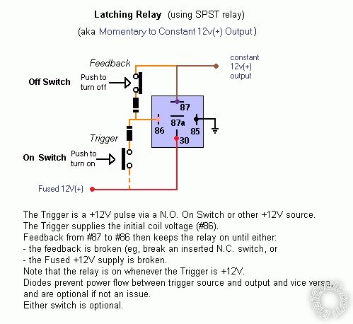
 Both the above come from eg
 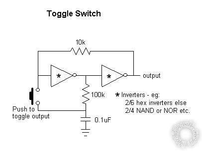 That's taken from
  There are also toggling latching relays as well as other special relays, but others know of them (I DIY my own circuits for "standard" relays).
Sorry, you can NOT post a reply.
This topic is closed.
 Printable version
| You cannot post new topics in this forum You cannot reply to topics in this forum You cannot delete your posts in this forum You cannot edit your posts in this forum You cannot create polls in this forum You cannot vote in polls in this forum |

| Search the12volt.com |
Follow the12volt.com 
Thursday, May 14, 2026 • Copyright © 1999-2026 the12volt.com, All Rights Reserved • Privacy Policy & Use of Cookies

Thursday, May 14, 2026 • Copyright © 1999-2026 the12volt.com, All Rights Reserved • Privacy Policy & Use of Cookies
Disclaimer:
*All information on this site ( the12volt.com ) is provided "as is" without any warranty of any kind, either expressed or implied, including but not limited to fitness for a particular use. Any user assumes the entire risk as to the accuracy and use of this information. Please
verify all wire colors and diagrams before applying any information.
