Hi everyone,
I've just installed a new sub in my car and I found a switch which was on cars with traction control. I'm trying to build a circuit so that I can use this button to turn off my sub. I'm going to do this by placing the switch+circuit on the remote wire running from the stereo to the sub. The problem is that the switch is a momentary open switch.
I've tried building this circuit but somehow I failed (maybe used the wrong relays?) and the button still acts as a momentary open one. And also, if I understand this setup correctly it will toggle the sub on upon the first press, and I'd like it to be on standard, and off after pressing the button.
The button I'm using is wired as follows:
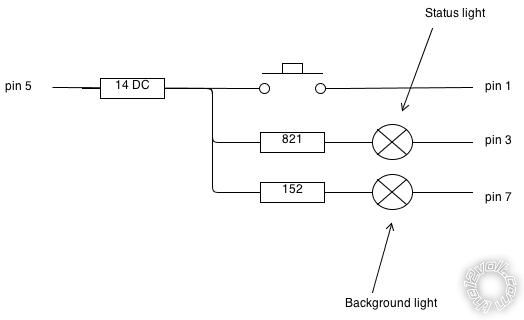
I created this scheme myself and I don't have any background in electronics so sorry if it's not correct!
So in short I'm looking for:
A circuit that will break the remote wire connection upon a button press. If the button is pressed again it would be cool if it were to re-enable the sub, but this is not a necessity.
I'd like to keep the background light on as long as there is a current on the remote wire coming from the radio and the status light must be on whenever the connection is closed and the sub is on.
Thanks!
Why not put a switch between the stereo and the remote?
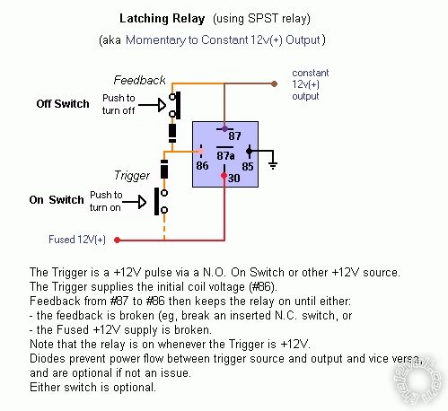
If the stereo has no remote, elsewhere I've posted the following circuit but that requires a 2nd switch to turn off, or interrupting the heavy +12V (to #30). (Note that the dashed +12V to the ON switch can be any +12V source.):
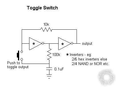
The problem is having a single switch toggle. It can be done using a T-type flip-flop, and I'll often suggest a 4017 counter in divide by 2 mode.
Otherwise I suggest a google image search for the pic you posted above. That will find similar pics and circuits.
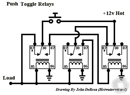
But John's circuit should work. Check that you have wired it correctly. The left 2 relays should come on and stay on when "clicked" on. The 2nd press should click the RHS relay which turns the others off, though it relies on having short button pushes. (If I decipher it correctly, the top switch should itself be switched to lock itself out after pushing...)
I'm sorry if I wasn't clear, but I was indeed intending to put the switch between the stereo and the remote cable.
Well thats the entire problem. The switch is a momentary open one, and I want to use this one, because it's build for the car and thus fits perfectly
If the amp has a remote, then use my circuit with "Fused +12V" being the stereo remote output and the "Constant +12V output" to the amp's remote.
Omit the off switch. When the stereo turns off, so will the amp (because the relay & +12V drops out).
Sorry. Overnight I had a D'oh moment regarding my reply(s). I think I've been confusing this with another
parallel thread, and I certainly missed that you said it was a momentary on switch.
If you use my above circuit, unless switching the amp power itself (and hence taking +12V from the battery while the switch is powered from the stereo's remote output), then you don't need the diodes. They are only there to ensure the load current (the amp's remote on) does not go through the (low current) switch(es) whilst the relay is switching over.
But your switch should be able to handle such current. (Amp remotes are usually from tens of mA to ~2A.)
But an equivalent to my circuit is:
Both the above come from eg
capacitor value for latching relay?.
But if you want to be able to toggle the amp on & off and the switch can be floating or isolated - ie, its in & out independent of +12V or GND (which should be possible assuming its indicator LED/lamp is independent, if fitted) - then maybe this circuit:
That's taken from
latched on/off momentary w/ brake kill which also has another of Hotwaterwizard's latching circuits but that requires a separate off switch (it's
logically or electrically equivalent to my relay circuit above but using 2 momentary on switches (not mom-on and mom-off/break) and 2 relays).
[ PS - albeit more for other readers and a note to myself! I just realised, without an extra resistor, those hex inverters cannot be "open collector" types. But if OC types, the spare 3 or 4 inverters could be used in parallel to "sink" bigger loads. But inverter chips like other
gates (NAND, NOR etc) normally have
active hi & low outputs; they will specifically state if they are OC (Open Collector).
]
Also for toggling, there is always the 14-pin
4017 "one of 10 decade counter" chip with the switch clocking it; its 0-output pin unconnected, "1" goes to a relay unless it has enough drive for the target circuit (remote on); and "2" is connected to its Reset pin - ie, a divide by 2 counter. [That link numbers 4017 outputs from 1 to 10. Most will number them 0 to 9 as I do.]
That IMO is a bit overkill for a "simple" divide by 2 or 2-way circuit, but SAAB and probably others use it for their headlamp hi/low beam dipper relay instead of using other transistor or flip-flop circuits, probably because it is so easy to do.
Ok, that solved
my confusion. How about yours?

There are also toggling latching relays as well as other special relays, but others know of them (I DIY my own circuits for "standard" relays).