Normally Closed Starter Kill Relay
Normally Open Starter Kill Relay
Passive Starter Kill Diagrams
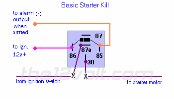
Normally Closed Starter Kill Relay
The basic starter kill relay diagram shown below, breaks continuity
of the lead from the ignition switch to the starter motor (or in some
cases i.e.; Ford, to another relay), when the alarm is armed and the ignition
is turned on. This is the most commonly used application for disabling
the starter. Click
here for another starter kill diagram.
 page menu
| next
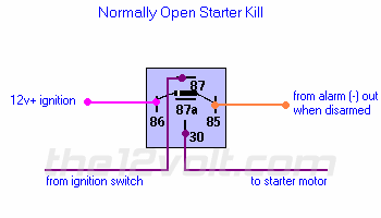
Normerly Open Starter Kill
This normally open starter kill relay application below relies
on a ground from the alarm when disarmed and 12 volts (+) from the ignition
to enable the driver to start the vehicle. * Note: most alarms with this
feature will not provide this grounded output when power ,12 volts (+),
to the alarm is not present, even if the alarm is grounded.
 previous
| page menu
| next
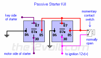
Passive Starter Kill
This is a stand alone starter kill. It does not rely on an
alarm or keyless entry for it to work, only a simple momentary contact
switch (normally open) to deactivate it. Every time the ignition is turned
off, continuity is broken on the starter feed wire. To disable (or start),
turn ignition on, then press the hidden switch, then start as normal.

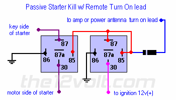
You can substitute the switch with a number of others devices such as the
amp turn on lead of your head unit. Be sure to isolate it with at least a 1 amp diode.
Turn the key to the run position. Allow the head unit to come on or turn it on.
Now start the vehicle. If you connected to the power antenna lead, make sure the tuner is on.
If you have a pullout or detachable face head unit, your vehicle will not start witout it.
 previous
| page menu
