Constant to Momentary Output
Momentary to Constant Output
Stereo to Bridged Mono Switched Outputs
Basic Remote Start Relay Diagram
One Channel to Multiple Outputs
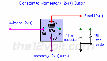
Constant to Momentary Output
The capacitor allows the
coil of the relay to be energized until the capacitor stores a charge,
thus de-energizing the coil. The resistor bleeds off the charge of the
capacitor when positive voltage is removed from the other side of the coil. You
can increase the output time by simply changing the value of the capacitor.
This one will give you about a 1/2 second output..
 page menu
| next
Momentary to Constant Output
page menu
| next
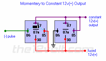
Momentary to Constant Output
Once activated by the relay on the left, the relay's coil on
the right will stay energized until either ground or 12v(+) is removed.
You can do this with another relay. Or try connecting to a 12v(+) switched
source instead of a constant one. Or you can have a door trigger activate
a relay to break continuity. The variations are practically endless.
 previous
| page menu
| next
Stereo to Bridged Mono Switched Outputs
previous
| page menu
| next
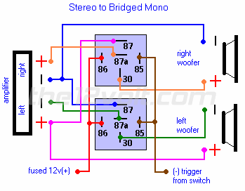
Stereo to Bridged Mono Switched Outputs
If your amplifier is capable of running in dual mode or mono,
and is configured to run mono by using the left channel positive and the
right channel negative outputs, then the diagram to switch between stereo
and mono to the same pair of speakers (mostly woofers) is as shown below.
Remember this will decrease the impedance by 1/2 and in
theory double
the power output of the amplifier.
Be sure to check the specifications of your amplifier first.
 previous
| page menu
| next
One Channel to Multiple Outputs
previous
| page menu
| next
One Channel to Multiple Outputs
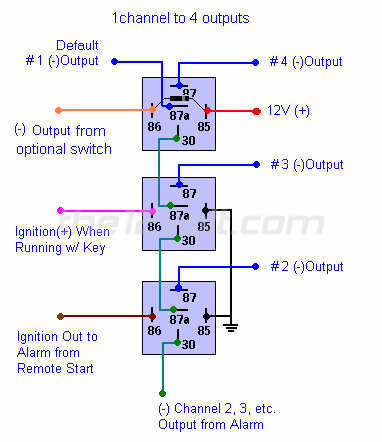
You can add multiple functions to an AUX ouput of an alarm or keyless entry
by adding a relay in series with the output lead as shown to any switch or accessory with an output.
Only one ouput can be active at anytime, the one first in the chain (bottom relay in diagram) will
have priority, so if you wanted to have the ignition from the key to have priority over the ignition from the remote start,
you would connect it to the first relay and the output of the remote start to the next and so on. Also pay attention to the top
relay shown. Terminal #87a (the default output) will be active only when none of the coils of the relays are energized. There are many other
accessories that can be used with this, including the remote turn on lead and/or power antenna lead of your head unit.
 previous
| page menu
| next
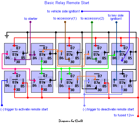
Basic Remote Start Relay Diagram
previous
| page menu
| next
Basic Remote Start Relay Diagram
DO NOT INSTALL this or any other remote
start system in a vehicle with a STANDARD TRANSMISSION.
The
consequences should be obvious. Below is a basic relay remote start system.
It is
not shown with any inhibits, nor a single trigger to activate
and deactivate it, and does
not have "rev protection".
You are
much better off with a system you can purchase from a local dealer or retailer.
They include many important safety features and come with a warranty, unlike
the one below. But if you must make one from relays, here are the basics
(shown below
without the diodes across the coils). You will have
to customize this to work with the vehicle
you plan to install it into. Make note of each wire's function in the harness
connected to the back of the ignition switch. You will have to duplicate
these in order to have a successful installation.
Only advanced installers
should attempt this. I have made several of these and they are still
on the road today. I included timers and inhibits in them to perform the
same as a manufacture's piece. But I still prefer to use theirs. It takes
less time to install from start to finish and theirs is a whole lot smaller.
 previous
| page menu
| read me
previous
| page menu
| read me