wiring dual underhood batteries
Printed From: the12volt.comForum Name: Car Audio
Forum Discription: Car Stereos, Amplifiers, Crossovers, Processors, Speakers, Subwoofers, etc.
URL: https://www.the12volt.com/installbay/forum_posts.asp?tid=124312
Printed Date: May 16, 2026 at 9:48 AM
Topic: wiring dual underhood batteries
Posted By: edouble101
Subject: wiring dual underhood batteries
Date Posted: November 06, 2010 at 8:59 PM
I plan on wiring two D3400's in my engine compartment. One battery on the left fender (driver's side) and one on the right (passenger side). I have put alot of thought in this and I do not want a secondary battery in my trunk. My vehicle came equipped with one battery on the driver's side.
I am powering 3500wrms. I have a 180 DC Power alternator. I am using all 1/0 power wire and ground wire.
Which of these two diagrams that I drew up would be better, ie. hold voltage and supply amperage to my trunk mounted amplifiers?
Thank you!


I am powering 3500wrms. I have a 180 DC Power alternator. I am using all 1/0 power wire and ground wire.
Which of these two diagrams that I drew up would be better, ie. hold voltage and supply amperage to my trunk mounted amplifiers?
Thank you!
Replies:
Posted By: edouble101
Date Posted: November 06, 2010 at 9:00 PM
BTW as per forum rules : 2008 Hyundai Elantra
Posted By: edouble101
Date Posted: November 06, 2010 at 9:16 PM
I should also add that I will be listening to the stereo with the car on only. No need for relays and solenoids.
Posted By: haemphyst
Date Posted: November 07, 2010 at 9:32 AM
TECHNICALLY it doesn't matter. Notice and heed that word. NO connection is perfect.
I would personally use the second one, simply because it is one less connection (and really... it's three less connections - terminal one to wire, terminal two to wire, and and two terminals to a vibration prone alternator output. Too many additional places for error and resistance.) between battery #2 (the starting battery, as you have it labeled) and the amplifiers.
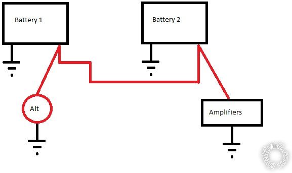
Also, forget the "jumper" on the negative terminals altogether, whichever digram you choose. Proper, solid connections to the chassis will do all that you need them to do. Also, you are completely correct, there *IS* no need for relays or solenoids, but really, there never is! :)
I would personally use the second one, simply because it is one less connection (and really... it's three less connections - terminal one to wire, terminal two to wire, and and two terminals to a vibration prone alternator output. Too many additional places for error and resistance.) between battery #2 (the starting battery, as you have it labeled) and the amplifiers.
Also, forget the "jumper" on the negative terminals altogether, whichever digram you choose. Proper, solid connections to the chassis will do all that you need them to do. Also, you are completely correct, there *IS* no need for relays or solenoids, but really, there never is! :)
Posted By: edouble101
Date Posted: November 07, 2010 at 9:53 AM
I like simplicity and minimal connections! Thanks for your comment about this.
Posted By: oldspark
Date Posted: November 07, 2010 at 7:38 PM
I agree. #2.
Your problem will be the voltage drop from the front to the back.
And the heavy inter-battery +12V connections make the alternator connection irrelevant (normally the alternator is to one battery only).
Of course, being permanently connected means a (rated) 5 year life and no protection if you leave the amp on.
Posted By: edouble101
Date Posted: November 07, 2010 at 7:47 PM
oldspark wrote:
I agree. #2.
Your problem will be the voltage drop from the front to the back.
And the heavy inter-battery +12V connections make the alternator connection irrelevant (normally the alternator is to one battery only).
Of course, being permanently connected means a (rated) 5 year life and no protection if you leave the amp on.
I do not know what you mean by a rated 5 year life? The will not be a voltage drop front to back but possibly an amperage drop.
I put a decent amount of thought into this. A rear mounted battery is exposed to a different temperature than an engine compartment mounted battery which affects charging rates and discharge rates. And there is also a charging amperage drop between the front and rear battery due to wire resistance. So I figured that I would give up a couple amperes due to wire resistance to have battery longevity. Plus I just have a better piece of mind adding a second battery under the hood versus in the trunk. Is my thinking correct?
Posted By: oldspark
Date Posted: November 07, 2010 at 8:14 PM
edouble101 wrote:
There will not be a voltage drop front to back but possibly an amperage drop.....
And there is also a charging amperage drop between the front and rear battery due to wire resistance...
No - the current is the same!
There is a voltage drop, not a current drop. Remember - current is the SAME through a series circuit.
The voltage drop along the cable is V = IR where I is the current through the cable's resistance R.
The rated or design life of that battery is 10 years.
Hence - in simple terms - two such batteries in parallel halves the design life to 5 years.
That's using its rated life as a reliability figure.
But wiring two batteries in parallel doubles the probability of failure where that prob of failure is for self induced failure during normal use.
That's simple reliability theory - if an interconnected system doesn't increase reliability, it reduces it. Since a failed parallel battery will fail the other battery, it's a negative effect (a good battery won't hold up a bad battery).
There are other factors - like for normal cranking, the parallel arrangement will extend life (because the current drain and discharge depth is lower)...
But suffice to say, if one battery goes down, so does the other.
EG - Two new "10 year" D3400s in parallel. One fails after 3 months (due to manufacturing fault - say a collapsed cell or 2) which fails the other. Hence after 3 months (or 3 months and 1 week) you have 2 dead batteries. Warranty claim? Maybe for the first, but good luck for the 2nd.... And for some brands, good luck for the first!
Posted By: edouble101
Date Posted: November 07, 2010 at 8:43 PM
oldspark wrote:
edouble101 wrote:
There will not be a voltage drop front to back but possibly an amperage drop.....
And there is also a charging amperage drop between the front and rear battery due to wire resistance...
No - the current is the same!
There is a voltage drop, not a current drop. Remember - current is the SAME through a series circuit.
The voltage drop along the cable is V = IR where I is the current through the cable's resistance R.
The rated or design life of that battery is 10 years.
Hence - in simple terms - two such batteries in parallel halves the design life to 5 years.
That's using its rated life as a reliability figure.
But wiring two batteries in parallel doubles the probability of failure where that prob of failure is for self induced failure during normal use.
That's simple reliability theory - if an interconnected system doesn't increase reliability, it reduces it. Since a failed parallel battery will fail the other battery, it's a negative effect (a good battery won't hold up a bad battery).
There are other factors - like for normal cranking, the parallel arrangement will extend life (because the current drain and discharge depth is lower)...
But suffice to say, if one battery goes down, so does the other.
EG - Two new "10 year" D3400s in parallel. One fails after 3 months (due to manufacturing fault - say a collapsed cell or 2) which fails the other. Hence after 3 months (or 3 months and 1 week) you have 2 dead batteries. Warranty claim? Maybe for the first, but good luck for the 2nd.... And for some brands, good luck for the first!
Gotcha.
When looking over wire gauge charts I normally see amperage lost over a specific distance. I rarely read about voltage lost. Tricky.
Posted By: oldspark
Date Posted: November 07, 2010 at 10:34 PM
edouble101 wrote:
When looking over wire gauge charts I normally see amperage lost over a specific distance. I rarely read about voltage lost.
I suspect you misinterpret....
Amperage is never lost thru a wire or component.
But the longer the wire, the higher the resistance, hence less current travels through it.
(Ohms Law: V = I x R. The voltage V across something is equal to the current through it times its total resistance.)
The thinner a water pipe, the less water travels through it, but the water is not "lost" along the way.
(A smaller pipe diameter is increase Resistance; Current is the water flow (quantity or rate); Voltage is the pressure drop.
edouble101 wrote:DEFINITELY!!
Tricky.
Not difficult - merely tricky & confusing (and may be difficult to grasp).
Thereafter it's not difficult - though I will probably NEVER say it is NEVER tricky - I still get tricked/confused when I know better....
PS - WRT paralleling 2 batteries, you have minimised any inequality except for their interconnection (see pic below) by having batteries of the same type & batch and age and history and temperature....
I compliment you on agreeing that trunk & engine bay difference mean temperature differences hence they re NOT the same battery (wrt behavior).
Mind you, there are many that say it is fine to parallel batteries - eg - see jmelton86's "Not only is it done all of the time, with mismatched batteries alot of the time" in the12volt's 2 batteries (though no mention is made of their reliability or thermal runaway for AGMs etc...).
I'll stick to my simple reliability and interaction statement above. I'll let others disprove it and counter (IMHO) the expert claims and findings.
As top the final detail - the interconnection to ensure equal loading and charging (sorry - I don't know the author or web source):
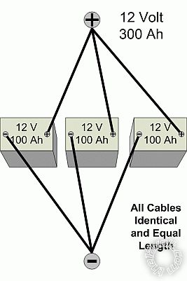
Or from the above link:

(The 2nd "Parallel" version is better - it ensures equal current through BOTH batteries.)
Posted By: edouble101
Date Posted: November 08, 2010 at 4:06 AM
Thank you oldspark for discussing this with me. I am definitely using the two batteries in parallel I do not have a 24v system!!
Posted By: oldspark
Date Posted: November 08, 2010 at 5:15 AM
LOL! I assumed - or hoped! - that that was obvious. (A big bad oops if it wasn't.)
I was too lazy to edit the pic. (Actually I just used what was already there (on 12volt).)
My preference is always to connect parallel batteries ONLY when charging, else when required in parallel - eg, for winching or cranking.
But that's because I have a charge light and use that for all the smarts (ie, "smart isolator") - just add a relay.
And because I always want a cranking battery no matter how much I've flattened the other battery...
Posted By: edouble101
Date Posted: November 08, 2010 at 5:34 AM
Do you see any reason why I should have two runs of 1/0 wire to the trunk to minimize any voltage drop?
Right now my plan is only one run of 1/0 to the trunk.
Right now my plan is only one run of 1/0 to the trunk.
Posted By: edouble101
Date Posted: November 08, 2010 at 6:05 AM
FYI I will be using an Alumapro cap5 v2 mounted very near the amplifiers as well.
Posted By: oldspark
Date Posted: November 08, 2010 at 6:10 AM
Yes - because that will HALVE the voltage drop (along the +12V cable).
But it depends what your requirements are....
But you may understand why the second battery is usually mounted near the amplifier.
And why many will double up on the ground connections because they are shorter (battery to gnd; amp to gnd; chassis is gnd in between).
3500 W RMS - let's say 350A at max output.
A 180A alternator at max output.
So 350-180 = 170A from batteries; say 90A each @ 0.004 Ohms internal resistance (assumed; fully charged) hence 0.36 voltage drop at terminals hence a system voltage of say 12.8-.36 = 12.45 Volts.
12.45V with 350A thru 1/0 = ~0.1 Ohms per 1000' = 35V per 1000' = 0.35V drop over 10'.
So 12.45-.35 = 12.1V at amp with 3.5kW output & 180A alternator...
And so the calcs continue....
But for 1/0G (if 0.1 Oms resistance per 1000'), that's ~350A x 0.1/1000 = 0.035V drop per foot.
Posted By: edouble101
Date Posted: November 08, 2010 at 6:18 AM
So...one run of 1/0 will have 0.35 volt drop over 10' which is minimal. And my Alumapro cap5 will help keep voltage up during periods of high amplifier draw.
I should be good then, right?
Thank you very much!
I should be good then, right?
Thank you very much!
Posted By: oldspark
Date Posted: November 08, 2010 at 8:01 AM
A 1V drop (at the amp) with a 5F cap will take about 14 milliseconds.
(So in 1 second, power at 70Hz will have dropped about 20%.)
A small battery instead - say 1.2AH or 7AH - might perform much better than that cap.
(So in 1 second, power at 70Hz will have dropped about 20%.)
A small battery instead - say 1.2AH or 7AH - might perform much better than that cap.
Posted By: edouble101
Date Posted: November 08, 2010 at 8:57 AM
Ok, so now I am back to mounting a third much smaller battery in the trunk near the amplifiers. I am ok with this.
Since I am using XS Power batteries the smallest they make is the D680 which is 20ah. Would I then connect all batteries at the negative terminal including a chassis ground for each battery? Use one run of 1/0 or two runs of 1/0?
Thanks again for your input!
Since I am using XS Power batteries the smallest they make is the D680 which is 20ah. Would I then connect all batteries at the negative terminal including a chassis ground for each battery? Use one run of 1/0 or two runs of 1/0?
Thanks again for your input!
Posted By: oldspark
Date Posted: November 08, 2010 at 9:36 AM
Why not instead move your 2nd battery to the trunk?
It has no benefit in the engine bay.
It has no benefit in the engine bay.
Posted By: edouble101
Date Posted: November 08, 2010 at 9:53 AM
oldspark wrote:
Why not instead move your 2nd battery to the trunk?
It has no benefit in the engine bay.
You are right, I could do that. I have two reasons for mounting the second battery in the engine compartment.
1. Weight!!!!
My subwoofer weights 42lbs, the enclosure 60-80lbs and amplifiers 20-30 lbs. That is nearly 150lbs combined. The D3400 weights 46lbs. So total weight is nearly 200lbs. By mounting the secondary battery under the hood I could help reduce the additional weight being added in the trunk.
2. Both batteries should be charged and discharging equally. Although I have not done any testing that proves this true or not and to what extent.
It appears that there are advantages and disadvantages of both mounting options. Which one is ultimately best?
Posted By: oldspark
Date Posted: November 08, 2010 at 11:46 AM
edouble101 wrote:
Both batteries should be charged and discharging equally...
Only if in parallel, but that is not recommended anyhow....
Like I said, if one fails, you have 2 ruined batteries (unless you monitor and prevent the good battery being damaged).
Put it this way, if you follow the normal(??) practice of a battery next to the amps in the trunk, with an isolator:
- you won't need a cap;
- the charge & discharge rate won't matter;
- you won't have your amp discharge your cranking battery;
- you can use a cranking battery for the engine. (Though the amp's 350Amps is a cranking current.)
But it depends what you want, and what audio reserve time (& risking the ability to start the vehicle).
If you are space & weight limited, then 2 "diagonally" connected matched batteries as you proposed may be best - provided one doesn't fail prematurely.
And if short sags are an issue, then a cap - especially if you already have one. (Although a battery is better, you then have the paralleling issue.)
I would not have 2 batteries in parallel - I would use an isolator.
And hence matching is not an issue, and I would have the 2nd battery with the amps - ie, a wet-cell cranker, and AGM for the trunk.
But others reckon paralleling is fine....
Posted By: edouble101
Date Posted: November 08, 2010 at 2:32 PM
Oh man I am going to drive myself and you nuts over this, sorry! I am very much still learning the electrical side of this car audio installation.
I am scratching the dual under hood battery idea and am accepting your recommendations. I will mount the auxiliary battery in the trunk separated from the main battery with a battery isolator.
I know that I should use same brand batteries, main and auxiliary but will I see any advantages by upgrading the starting battery while using a battery isolator?
I am looking at a Stinger 500 amp isolator, is this one good? https://www.stingerelectronics.com/productDetails.aspx?Productid=89&CategoryID=2
Thank you very much for your responses. I learned more from your comments in the past two days than I have over a month!
Posted By: oldspark
Date Posted: November 08, 2010 at 6:14 PM
edouble101 wrote:
Oh man I am going to drive myself and you nuts over this....
Let me tell you a little secret... it is actually ME that is driving YOU nuts.
Have you noticed how quiet it is? That nobody else seems to have chimed in? Why is that?
I've been waiting for someone to say <whatever> is ok, or that they have <this> and it's fine.....
Yes. it's quite.
Too quiet! (LOL)
Firstly - there is no "best" solution except perhaps when you have specific requirements (& prioritised!).
Secondly - you are bluddy brilliant! You have a well thought out and valid original plan. You understood the need for MATCHING batteries that are hard-paralleled. Yet you can also see the other issue.... (at the expense of your design). [ As I wrote, many reckon you can parallel anything. That is an opinion. My opinion is that you can parallel anything - especially if you don't care how long it (doesn't) last (and that is my experience too). It's like you can use water instead of brake fluid for your vehicle's brakes; and it doesn't need an air or oil filter... ]
But enough of the non-tech ramble....
If rear weight or overall battery reserve or identical batteries etc is a higher priority than other things (like a .3V (whatever) drop), ten you have a great design. Note that I use "or" as in English or meaning and/or (it is now the equivalent of Logic or - writing &/or is no longer required), and I'll omit the paralleling issue.
As for isolators, IF you have an old-style alternator with a charge light, then I hater the smart isolators that are often marketed.
Why? Because the charge light provides all the functionality you need to control not-charging or not-running isolation switches for batteries, loads, fuel pumps etc.
Whilst smart switches can do that, they are ultimately voltage sensors and they require various delays to ensure proper or non-destructive operation.
And sine BOTH require a relay to do the connection (or a MOSFET etc), why not just use the relay WITHOUT all the added electronics?
(Alas this was recently discussed with somewhere, but I think the respondent now sees my point. However at least they pointed to the Blue Sea isolator that has a cut-out for cranking. Now why would they have that if other "perfect" smart isolators don't? LOL! And they dealt with marine systems that do not have charge lamps, so voltage sensing is one of the few options. But they could not answer why someone otherwise should spend money on an "isolator" when an ordinary relay will generally do the job, and do it in a far superior and reliable manner!)
So, do you have a charge lamp? (An alternator with a D+ terminal, else an L terminal (with others like perhaps S or I).) I found out yesterday that that include GM's "CS" type alternators.
Posted By: edouble101
Date Posted: November 09, 2010 at 8:55 AM
I think I have a D+ wire.
My alternator is a two wire type. It has a charging wire and a plug with two wires. The plug has a blue and a red wire. I think the blue wire is D+(?)
As far as no other comments.....I assume everybody else either agrees with you or does not have an opinion about this.
My alternator is a two wire type. It has a charging wire and a plug with two wires. The plug has a blue and a red wire. I think the blue wire is D+(?)
As far as no other comments.....I assume everybody else either agrees with you or does not have an opinion about this.
Posted By: oldspark
Date Posted: November 09, 2010 at 2:31 PM
Cool. 2 wires. (The charging = B or B+ = HEAVY +12V and the chassis/ground connections are never counted since they are implicit & essential.)
I/we should confirm alternator type later. But let's assume it is a charge-lamp type that turns off a dash lamp when it is charging. (And the dash lamp is usually required to provide a rotor tickle current to ensure initial charging (power generation). And usually it's called "D+" in single-wire alternators only and "L" in multi-wire alternators [why? so i can expend more verbiage!].)
Now, instead of commercial "battery isolators", I hereby present... (and old diagram that has been renewed, and I think with a better layout)...
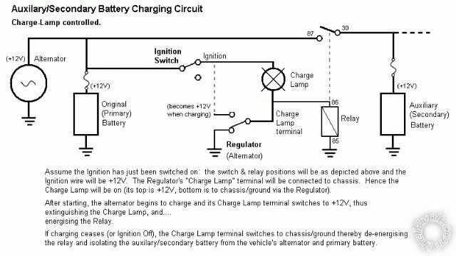
Or for those that think that is way too complicated, there is....
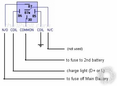
(Yes, I know it's the same as the other diagram, but circuits confuse people; labels don't.)
The upper circuit diagram describes its operation.
IMO, forget "smart" isolators that TRY to figure out when a vehicle is charging and when it isn't - and have various delays and voltage thresholds (sometimes adjustable) in an attempt to overcome various situations.
Instead go to the source and use its signal that indicates it is charging (or indicates it is not charging....).
Surely the Source's word is more reliable than some add-on circuitry (ie, a voltage-sensing "smart" isolator)?
Besides, if there are so many GOOD Smart Isolators out there, how come they have different voltage settings and different delays etc? Which is best? And why do some have an extra input from the starter solenoid to provide a cranking override? (ie, isolate the batteries during cranking).
Alas I present questions that IME (In My Experience) are rarely IF EVER answered - especially by those that push Smart(sic!) Isolators. (Of course silly people will answer thinking they'll help their cause LOL!)
But let me not get carried away....
Did I mention that most Smart(sic!) Isolators use a relay?
You too can add a relay to smart circuitry.
In fact why not just get a relay of your choosing and add that the the smart circuitry that already exists - ie, the D+ or L circuit?
Will that be cheaper than a similar relay with its "smart" circuit or "microprocessor controlled" circuitry that provides you with the best compromise... I mean, best "intelligence" that the system is charging?
[ LOL = Remember - a charge light is a merely glowing tungsten and nowhere near as smart as a decision making uPC, though LEDs do have the silicon that uPCs also use.... Alas, I really should cease this sarcasm... ]
The main complication or issue with the chargeLight method is if the circuit - aka L-circuit - is too weak to energise the relay. And we don't want to blow that circuit in the alternator. (The L-circuit is really part of the regulator, but since these are integral to modern alternators, herein the term "alternator" refers to both.)
Older external mechanical regulators had no problem - they use a relay to control the charge light.
Later external electronic regulators could also usually power relays.
But some newer - especially integral regulator - alternators; whilst able to "sink" enough current to light the charge lamp and other dash lamps (ie, Initial Ignition-On lamp tests), they may not be able to source enough current to energise a relay (eg, 250mA).
Or if you want a 500A relay/isolator that might require over 1 Amp to energise....
Anyhow, the above issue is easily overcome - usually by using a common small relay to power a larger relay (eg, a common ~250mA 30A-rated relay to provide a few Amps for more or larger relays).
And a $3 MOSFET could replace a 60A relay AND provide interfacing from charge-LEDs or uPC L-circuits. (FETs can pass many tens of Amps yet only require micro-Amps to turn on!)
Note that a charging light is really a non-charging light - it is on when the alternator is NOT charging (and the Ign is on).
That functionality is carried over to modern vehicles & their EMS.
But for those with the fail-safe "is-charging" light, it's a simple case of adding signal inversion AND an initial lockout until after cranking (if indeed that is desired - some want batteries paralleled for cranking).
Another complication is not having an alternator-controlled charge light. EG - some marine, motorbike, recreational vehicle etc systems that have permanent magnet aka "stator" charging systems.
But then what the heck are you reading this for? You have no choice but to use an "add-on" voltage sensing system (aka battery or smart isolator) else current sensing else existing charge indication system!
But for those with old alternators, a battery isolator is simply an added relay with up to several hundred Amp capability.
For later systems, a smaller relay may need to buffer such a big relay.
For very new systems, a FET may be required.
For a "universal kit" - maybe a $3 MOSFET (with a resistor or 2) that can be connected to ANY charge lamp and power ANY load up to (say) 60A to 120A, or a 15A to 15,000A capacity relay etc.
[ Why not - if people sell two 5c IN914 diodes in an ATS fuse body for $42 (to boost alternator outputs by 0.6V), then surely a DIY battery isolator for $10 that saves an expensive and riskier "smart" solution would sell well? Better still, sell it for $100 as the "DIY batery isolator - add WHATEVER sized relay you want, or as many relays (for as many secondary batteries) as you want. ]
(Or does that sound as ridiculous as 10c worth of diodes for $42? I've only seen a few dozen of those 42,000% markups sell. That's 420 ROIs.)
But now, sun's up. So it's bed time.
I'll review. And maybe resign (LOL). I may find that diagram update.
At least I have re-posted that diagram - I found that it wasn't that easy to find. Nor are my other related tid-bits here and there.
Other issues - battery size & type; when to parallel (or not to).
FYI: Until later, some links with some good or related info...
Caveat: These were found whilst searching my posts for that diagram - NOT from searching for good info in my posts...!
That diagram from eg, 2 batteries.
Quoting anonymous1 "The dual battery post to end all posts. This should be stickyd." choosing a second battery.
Since the battery interlink "each end" protection should IMO be self resetting circuit breakers rather than (non-monitored) fuses: Fuses or curcuit(sic) breakers? (some good design issues; padded out by later jest attempts).
Extending isolation to multiple batteries (or groups of batteries): 3 battery isolation.
Though far from explanatory and complete, how a bad hard-paralleled battery can wreck others. Also AGM thermal runaway (BattCaps are AGM batteries, not capacitors!) why did my battcaps melt?.
A potpourri of things; and confusion: an extra battery
And more on an extra battery's "batts and caps are NOT 'extra loads'" (they actually HELP the alternator) how to wire 2nd battery?
Now if I can only remember to link THIS thread for the above links...
And maybe one day extract the info for a concise well organised sticky.
Maybe...? - what a joke.
I/we should confirm alternator type later. But let's assume it is a charge-lamp type that turns off a dash lamp when it is charging. (And the dash lamp is usually required to provide a rotor tickle current to ensure initial charging (power generation). And usually it's called "D+" in single-wire alternators only and "L" in multi-wire alternators [why? so i can expend more verbiage!].)
Now, instead of commercial "battery isolators", I hereby present... (and old diagram that has been renewed, and I think with a better layout)...
Or for those that think that is way too complicated, there is....
(Yes, I know it's the same as the other diagram, but circuits confuse people; labels don't.)
The upper circuit diagram describes its operation.
IMO, forget "smart" isolators that TRY to figure out when a vehicle is charging and when it isn't - and have various delays and voltage thresholds (sometimes adjustable) in an attempt to overcome various situations.
Instead go to the source and use its signal that indicates it is charging (or indicates it is not charging....).
Surely the Source's word is more reliable than some add-on circuitry (ie, a voltage-sensing "smart" isolator)?
Besides, if there are so many GOOD Smart Isolators out there, how come they have different voltage settings and different delays etc? Which is best? And why do some have an extra input from the starter solenoid to provide a cranking override? (ie, isolate the batteries during cranking).
Alas I present questions that IME (In My Experience) are rarely IF EVER answered - especially by those that push Smart(sic!) Isolators. (Of course silly people will answer thinking they'll help their cause LOL!)
But let me not get carried away....
Did I mention that most Smart(sic!) Isolators use a relay?
You too can add a relay to smart circuitry.
In fact why not just get a relay of your choosing and add that the the smart circuitry that already exists - ie, the D+ or L circuit?
Will that be cheaper than a similar relay with its "smart" circuit or "microprocessor controlled" circuitry that provides you with the best compromise... I mean, best "intelligence" that the system is charging?
[ LOL = Remember - a charge light is a merely glowing tungsten and nowhere near as smart as a decision making uPC, though LEDs do have the silicon that uPCs also use.... Alas, I really should cease this sarcasm... ]
The main complication or issue with the chargeLight method is if the circuit - aka L-circuit - is too weak to energise the relay. And we don't want to blow that circuit in the alternator. (The L-circuit is really part of the regulator, but since these are integral to modern alternators, herein the term "alternator" refers to both.)
Older external mechanical regulators had no problem - they use a relay to control the charge light.
Later external electronic regulators could also usually power relays.
But some newer - especially integral regulator - alternators; whilst able to "sink" enough current to light the charge lamp and other dash lamps (ie, Initial Ignition-On lamp tests), they may not be able to source enough current to energise a relay (eg, 250mA).
Or if you want a 500A relay/isolator that might require over 1 Amp to energise....
Anyhow, the above issue is easily overcome - usually by using a common small relay to power a larger relay (eg, a common ~250mA 30A-rated relay to provide a few Amps for more or larger relays).
And a $3 MOSFET could replace a 60A relay AND provide interfacing from charge-LEDs or uPC L-circuits. (FETs can pass many tens of Amps yet only require micro-Amps to turn on!)
Note that a charging light is really a non-charging light - it is on when the alternator is NOT charging (and the Ign is on).
That functionality is carried over to modern vehicles & their EMS.
But for those with the fail-safe "is-charging" light, it's a simple case of adding signal inversion AND an initial lockout until after cranking (if indeed that is desired - some want batteries paralleled for cranking).
Another complication is not having an alternator-controlled charge light. EG - some marine, motorbike, recreational vehicle etc systems that have permanent magnet aka "stator" charging systems.
But then what the heck are you reading this for? You have no choice but to use an "add-on" voltage sensing system (aka battery or smart isolator) else current sensing else existing charge indication system!
But for those with old alternators, a battery isolator is simply an added relay with up to several hundred Amp capability.
For later systems, a smaller relay may need to buffer such a big relay.
For very new systems, a FET may be required.
For a "universal kit" - maybe a $3 MOSFET (with a resistor or 2) that can be connected to ANY charge lamp and power ANY load up to (say) 60A to 120A, or a 15A to 15,000A capacity relay etc.
[ Why not - if people sell two 5c IN914 diodes in an ATS fuse body for $42 (to boost alternator outputs by 0.6V), then surely a DIY battery isolator for $10 that saves an expensive and riskier "smart" solution would sell well? Better still, sell it for $100 as the "DIY batery isolator - add WHATEVER sized relay you want, or as many relays (for as many secondary batteries) as you want. ]
(Or does that sound as ridiculous as 10c worth of diodes for $42? I've only seen a few dozen of those 42,000% markups sell. That's 420 ROIs.)
But now, sun's up. So it's bed time.
I'll review. And maybe resign (LOL). I may find that diagram update.
At least I have re-posted that diagram - I found that it wasn't that easy to find. Nor are my other related tid-bits here and there.
Other issues - battery size & type; when to parallel (or not to).
FYI: Until later, some links with some good or related info...
Caveat: These were found whilst searching my posts for that diagram - NOT from searching for good info in my posts...!
That diagram from eg, 2 batteries.
Quoting anonymous1 "The dual battery post to end all posts. This should be stickyd." choosing a second battery.
Since the battery interlink "each end" protection should IMO be self resetting circuit breakers rather than (non-monitored) fuses: Fuses or curcuit(sic) breakers? (some good design issues; padded out by later jest attempts).
Extending isolation to multiple batteries (or groups of batteries): 3 battery isolation.
Though far from explanatory and complete, how a bad hard-paralleled battery can wreck others. Also AGM thermal runaway (BattCaps are AGM batteries, not capacitors!) why did my battcaps melt?.
A potpourri of things; and confusion: an extra battery
And more on an extra battery's "batts and caps are NOT 'extra loads'" (they actually HELP the alternator) how to wire 2nd battery?
Now if I can only remember to link THIS thread for the above links...
And maybe one day extract the info for a concise well organised sticky.
Maybe...? - what a joke.
Posted By: edouble101
Date Posted: November 09, 2010 at 8:50 PM
I have days worth of reading and research now! Lol I love it, more information the better!
Thank you so very much for your time oldspark!
PS. My vehicle does not have a charge lamp. I drive a 2008 Hyundai Elantra.
Thank you so very much for your time oldspark!
PS. My vehicle does not have a charge lamp. I drive a 2008 Hyundai Elantra.