1999-2002 Silverado Remote Start w/Keyless Pictorial
Printed From: the12volt.com
Forum Name: Car Security and Convenience - Alarm/Remote Start Pictorials
Forum Discription: Installer submitted Alarm, Keyless Entry, and Remote Start Pictorials from our Car Security and Convenience forum.
URL: https://www.the12volt.com/installbay/forum_posts.asp?tid=135786
Printed Date: May 23, 2026 at 5:00 AM
Topic: 1999-2002 Silverado Remote Start w/Keyless Pictorial
Posted By: kreg357
Subject: 1999-2002 Silverado Remote Start w/Keyless Pictorial
Date Posted: January 11, 2014 at 4:12 PM
This is a DIY Pictorial on installing a remote start with keyless entry system into a 1999 through 2002 Silverado. This pictorial specifically covers trucks with automatic transmissions and gasoline engines. The GMC full size Pickup ( Sierra ) will be the same for these years, too.
These trucks have the Passlock2 engine immobilizer system. There are many bypass modules available. Depending on your skill level and budget, you can use anything from "relays and resistor method " to the newer "data" style bypass modules. For this install, an iDatalink ADS TBSL PL bypass module was chosen. Due to the ease of access to the necessary wires, a "full function" bypass module was deemed un-necessary for this install.
Any quality remote start system can be used. This truck needs (+) Parking Light and (+) Door Lock outputs from the R/S system. While all R/S systems can provide (+) Parking Light output, most newer R/S systems only provide (-) door lock outputs, so either relays or a Directed 451M module is needed to make the (-) to (+) conversion.
For this install, an Avital 4103 remote start system and a Directed 451M door lock module was used. Below are the wire connections :
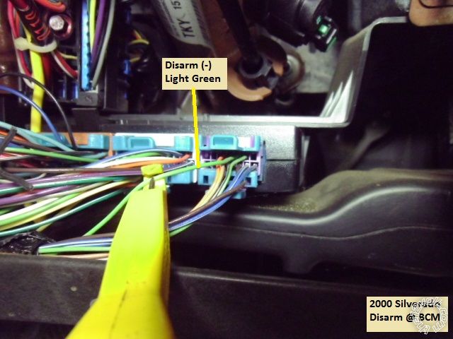
H1/1 LIGHT GREEN/ BLACK FACTORY ALARM DISARM Lt. Green (driver door key cylinder) (-) BCM, purple plug, pin B3
H1/2 GREEN / WHITE FACTORY REARM not used
H1/3 YELLOW (+) IGNITION OUT (TO ALARM) not used
H1/4 WHITE/ BLUE (-) ACTIVATION INPUT not used
H1/5 ORANGE (-) GROUND WHEN LOCKED not used
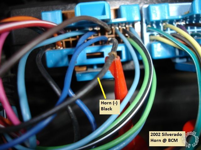
H1/6 BROWN (-) HORN OUTPUT Black (-) BCM, brown plug, pin A9
H1/7 RED / WHITE (-) TRUNK RELEASE OUTPUT not used
H1/8 BLACK GROUND Chassis Ground ( also has ADS TBSL PL Black wire )
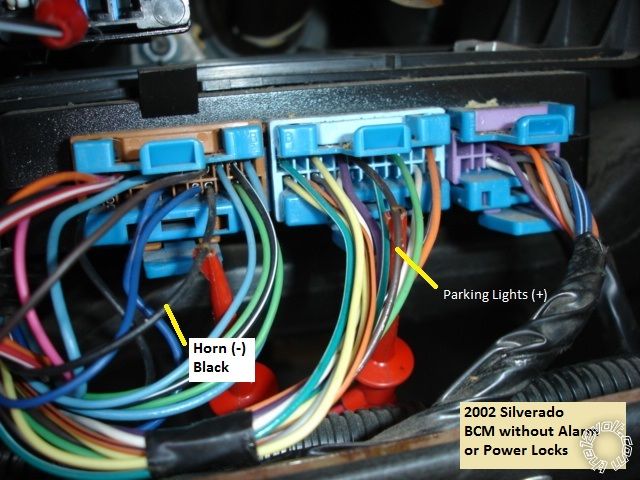
H1/9 WHITE (+/-) LIGHT FLASH *** Set to (+) *** Brown (+) BCM, lt. blue plug, pin B6
H2/1 BLACK/ WHITE (-) NEUTRAL SAFETY SWITCH INPUT Chassis Ground ( auto trans only! )
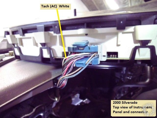
H2/2 VIOLET/WHITE TACHOMETER INPUT WIRE White (ac) instrument cluster
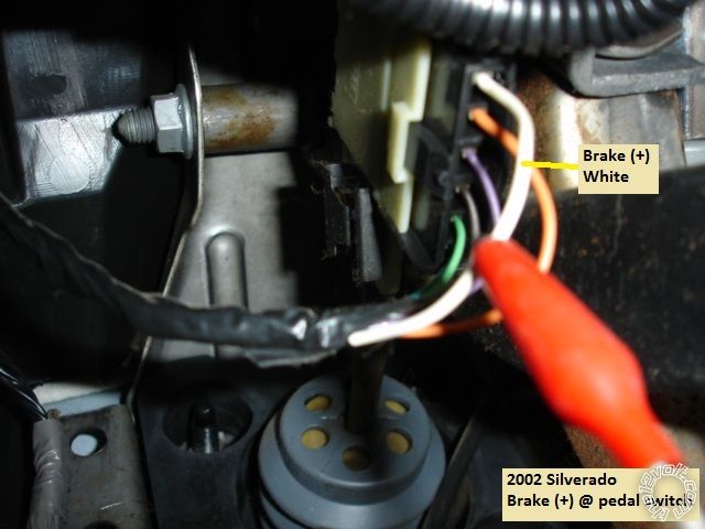
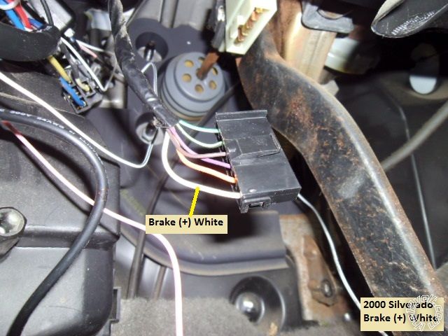
H2/3 BROWN (+) BRAKE SWITCH SHUTDOWN WIRE White (+) brake switch
H2/4 GRAY (-) HOOD PINSWITCH SHUTDOWN WIRE to Avital kit supplied hood pin
H2/5 BLUE/WHITE (-) 200mA 2ND STATUS/DEFOG OUTPUT not used
4-pin satellite harness diagram
1 BLUE STATUS OUTPUT to ADS TBSL PL Blue/White @ 4 pin connector
2 ORANGE (-) ACCESSORY OUTPUT to extra Relay Pin 85
3 PURPLE (-) STARTER OUTPUT not used
4 PINK (-) IGNITION OUTPUT not used
Heavy gauge relay wiring diagram
1 PINK (+) (30 AMP) OUTPUT TO IGNITION CIRCUIT Pink (+) ignition harness ( also has ADS TBSL PL Pink wire )
2 PURPLE (+) (30 AMP) OUTPUT TO STARTER CIRCUIT Yellow (+) ignition harness
3 ORANGE (+) (30 AMP) OUTPUT TO ACCESSORY CIRCUIT Orange (+) ignition harness
4 RED (+) (30A) HIGH CURRENT 12 INPUT Red (+) ignition harness ( also has 451M Violet/Black wire )
5 PINK/WHITE (+) PROGRAMMED FOR IGNITION2 White (+) ignition harness
6 RED (+) (30A) HIGH CURRENT 12V INPUT RED / White (+) ignition harness ( also has ADS TBSL PL Red wire )
Door lock harness, 3-pin connector
1 BLUE (-) UNLOCK OUTPUT plug in Directed 451M connector
2 EMPTY NOT USED plug in Directed 451M connector
3 GREEN (-) LOCK OUTPUT plug in Directed 451M connector
Extra 30/40 Amp SPDT relay for Brown ACC2 wire :
Relay Pin 85 to Avital ORANGE (-) ACCESSORY OUTPUT
Relay Pin 86 and 87 to Silverado RED / White (+) ignition harness through 30 Amp fuse
Relay Pin 30 to Silverado Brown ACC2 wire @ ignition harness
Relay Pin 87a not used
ADS TBSL PL
4 Pin plug
Red to Avital heavy gauge RED / White wire
Black to Avital H1/8 Black wire
Blue/White to Avital BLUE (-) STATUS OUTPUT
9 Pin plug
Pink to Avital heavy Pink IGN1 wire
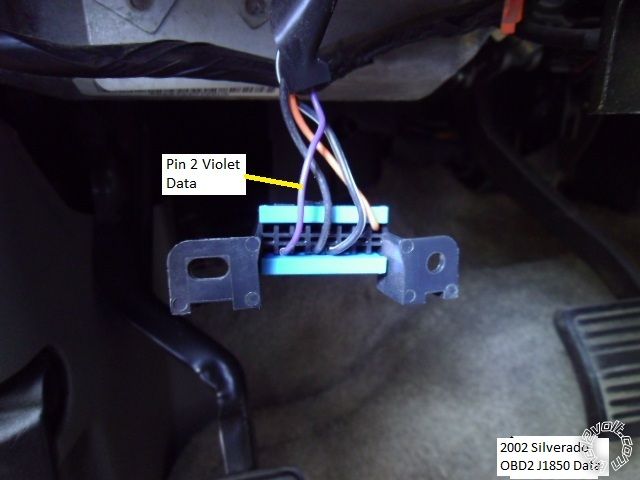
Orange to Silverado Violet wire @ OBD2 Pin 2
Directed 451M
3 Pin plug to Avital Door Lock connector
Violet/Black w/15 Amp fuse to Avital Red wire ( which goes to Silverado Red @ ignition harness )
WHITE/ Black not used
BROWN / Black not used
GREEN/ Black to Silverado Lt. Blue (+) BCM, brown plug, pin A4
Blue/Black to Silverado White (+) BCM, brown plug, pin A3
A few notes : This truck had the Factory Alarm and power door locks, some don't. The wiring above reflects that. I chose to power the Brown ACC2 wire during remote start and therefore needed an additional high power output. The extra relay handled this additional ignition circuit. The ADS TBSL PL handled the Passlock2 bypass via its' lone connection to the Violet wire at Pin 2 of the OBD2 connector. Very easy, very reliable but more expensive than other methods. Because of this, I did not get a photo of the Passlock2 wires that are typically used with other bypass modules.
Disassembly :
Set the tilt steering wheel to its' lowest position. Turn the ignition key to ON, press the brake pedal and move the gear selector to the bottom position. Remove the instrument cluster bezel by pulling it straight away from the dash. Remove the four 7mm screws that retain the instrument cluster and gently pull the cluster out. There is no need to disconnect the cluster harness, as there is plenty of slack in the harness. Lay the cluster on the dash. Move the shifter back to Park and remove the ignition key. Raise the tilt steering to it's highest position. Remove the two screws at the bottom corners of the lower dash panel, then
pull it straight away from the dash.
Remove the four 10mm nuts shown using a deep socket and then remove the metal plate.
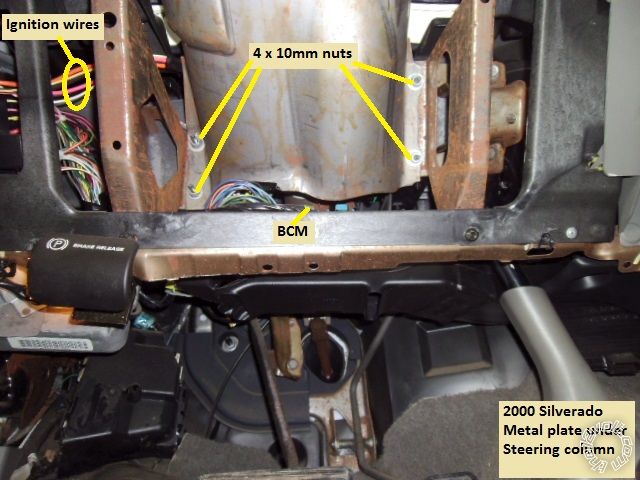
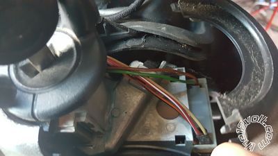
At this point the BCM and ignition wires are accessible. No need to remove the steering column covers.
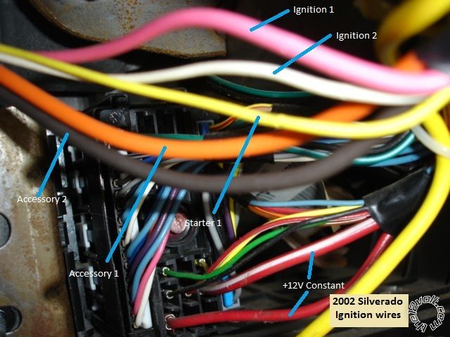
Wires:
This is a picture of the main ignition wires as they leave the left side of the steering column and pass above the BCM.
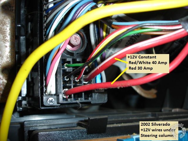
This is a close-up photo of the +12V constant wires :
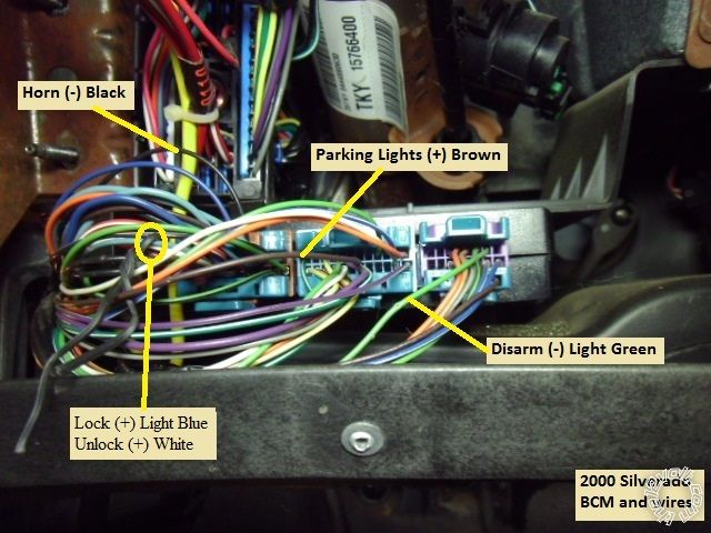
This is a shot of the BCM with the necessary wire marked :

This is a close-up of the Horn wire at the BCM :
This is a close-up of the Parking Light wire ( and Horn ) at the BCM :
If your truck has the Factory Alarm, here is a photo of the Disarm wire :
These are pictures of the Bake wire :
This is a photo of the Tach wire ( instrument cluster removed and resting on dash ) :
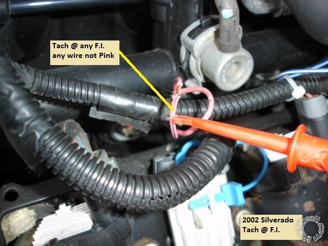
Here is a picture of another Tach source, any Fuel Injector :
Here is a picture of the OBD2 connector and the Violet Data wire at Pin 2 :
Firewall pass-through is available at the main wiring harness grommet and exits behind the vacuum brake reservoir.
While this Pictorial shows the necessary wires, you should still locate and verify these connection points with a Digital Multi Meter before soldering on the R/S's wires.
The parts used for this install ( Avital 4103 = $50, ADS TBSL PL= $40, 30/40 Amp SPDT Relay w/harness = $4, inline ATC fuseholder with 30 Amp fuse = $3 & DEI 451M = $9 ) cost around $106. This is probably less that getting a replacement factory keyless entry FOB with programming from the dealer. ------------- Soldering is fun!
Replies:
Posted By: pts760
Date Posted: February 16, 2014 at 11:33 AM
Aren't those lock/unlock wires at the brown plug on the BCM (+) trigger not (-) trigger.
-------------
I drink current, eat ohms, and bleed voltage
Posted By: kreg357
Date Posted: February 16, 2014 at 3:23 PM
Good catch, PTS760! I completely missed that error. The Lock wires in these trucks are definitely (+). ( Need to hire a proof reader...)
Here is an updated photo with the corrected wire polarities :
Additionally, there is a mixture of photo's in the Pictorial. Some from a 2002 without power locks and some from a 2000 with power locks and alarm. ------------- Soldering is fun!
Posted By: shesachevy99
Date Posted: April 16, 2014 at 10:52 PM
I'm currently installing a viper remote start on my silverado and I'm getting a 12v reading on my factory disarm. Why am I getting this reading?
-------------
The thing about them Chevy's is they always get you home. Just kick the fuel pump a few times
Posted By: auto enhancers
Date Posted: April 17, 2014 at 8:52 AM
because it rests at 12 volts, it is triggered by ground.
Posted By: kreg357
Date Posted: April 17, 2014 at 10:00 AM
As auto enhancers said.  You are looking for a (-) pulse signal. The wire at rest could be +12V or a float You are looking for a (-) pulse signal. The wire at rest could be +12V or a float
The correct DMM setup for locating a (-) type signal in a vehicle is : DMM set to 20V DC, Red test lead to +12V constant, Black test lead to the suspect wire. The DMM will briefly read +12V when the (-) signal is present. The Horn and Disarm wires shown above are (-) type signals and can found using the above setup. You could do this test with the Horn wire first ( you can reach the horn button and hold it to see the DMM results ) to get a feel for it. Auto-ranging DMM's will react slower and very brief (-) pulse signals will be difficult to catch.
For wires like these in older vehicles, I use a "Computer Safe" LED test light like the one pictured below :
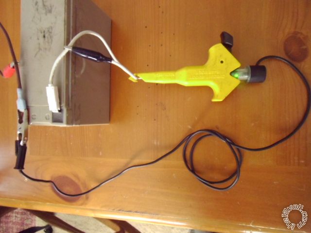
It draws only 3mA and will give a Green LED indication when the signal is present. It reacts quicker than a DMM and the Green LED is bright and easy to see. The (-) Disarm photo shows the LED tester attached to the wire but does not include the upper section of the tester with the LED. ------------- Soldering is fun!
Posted By: shesachevy99
Date Posted: April 17, 2014 at 11:38 AM
Thank you! I realized that after a good sleep.
-------------
The thing about them Chevy's is they always get you home. Just kick the fuel pump a few times
Posted By: boricua bob
Date Posted: April 26, 2014 at 2:56 PM
where is the door trigger located, and the wait to start(im doing a 2001 3500 LS) and can i still use the same tach for the disel like ur picture says or do i have to use a diffrent tach?
Posted By: kreg357
Date Posted: April 26, 2014 at 3:23 PM
The White Tach wire at the back of the instrument cluster will work for the Diesel Engine.
Info from AudioVox for the Door Trigger :
All Door Trigger TAN/LIGHT BLUE (-) @ KEYLESS MODULE BELOW STEERING COLUMN Info from ReadyRemote for the door trigger :
Door Trigger Tan (-) @ BCM, purple plug, pin B4 ( This is only the Drivers Door. ) Info from Bulldog Security :
TAN (-) for the Drivers door located in PURPLE PLUG, PIN B4
PASSENGER door use a ORANGE (-) in the PURPLE PLUG, PIN B2 or a DK BLUE/WHITE (-) in a LT BLUE PLUG, PIN B11
when connecting an alarm you must use both wires and diode isolate.
Wait to start Dark Blue (need to diode isolate see Tech Doc 1090) - @ instrument cluster harness. Here is a link to a ZIP file that includes TechTip 1090 : https://www.the12volt.com/installbay/file.asp?ID=1076 If your R/S system is capable you could use a Fixed Time Diesel Delay. ------------- Soldering is fun!
Posted By: boricua bob
Date Posted: April 26, 2014 at 3:48 PM
i'm installing a viper 5706v so i don't need the wait to start? what happens if i don't diode isolate the door trigger. i didn't do it on the 01 civic and everything works. i just connected the three wires together...
Posted By: kreg357
Date Posted: April 26, 2014 at 4:44 PM
Using the Viper's actual Wait To Start wire will allow the engine to crank as soon as the dash light goes off. Not connecting the WTS wire and using a Fixed Wait To Start time value ( 15 seconds ) will crank the engine after this time period ends. The choice is yours. See Menu 3, Item 9 for more options.
Diode isolation of the door triggers is used to prevent the vehicle from getting confused. If you have a vehicle that displays the two ( or four ) individual doors graphically, it will show the one that is open. If you connect the alarm without diode isolation, when one door is open, the graphic dash display will show all doors as open ( due to feedback ).
The 1N4001 diodes are available at RadioShack. ------------- Soldering is fun!
Posted By: boricua bob
Date Posted: April 26, 2014 at 5:00 PM
thanks ur always a big help...
Posted By: boricua bob
Date Posted: April 26, 2014 at 5:49 PM
I'm using the 556Lw and I need to know which and were is the wire on the truck so that I can cut and connect for the yellow and the BLACK / YELLOW..thanks
Posted By: kreg357
Date Posted: April 27, 2014 at 1:00 AM
Not sure on that truck. I have been using Data style bypass modules that only connect to the ODB2 Violet wire on those trucks for awhile now. Look for a bundle of three thin wires grouped together coming down the steering column. They can be White, Black & Yellow or RED / White, ORANGE / Black & Yellow. The Black or ORANGE / Black will test as ground and the Yellow will be between +1.2VDC and +4.7VDC when the key is in the ON position.
------------- Soldering is fun!
Posted By: boricua bob
Date Posted: April 27, 2014 at 12:54 PM
thanks again kreg357 couldn't of done it with out ur help. i finished around 2am. and everything work great. for the door trigger i use the TAN (-) for the Drivers door located in PURPLE PLUG, PIN B4
PASSENGER door use DK BLUE/WHITE (-) in a LT BLUE PLUG, PIN B11. the passenger door trigger is aslo for the rear doors on a crew cab. and for the bypass 556LW u can take the steering colum cover off and there is three wires and u can use the yellow one or u can cut and use the same wire at the ignition harness right above the +12V constant RED / white 40Amp wire.
Posted By: kreg357
Date Posted: April 27, 2014 at 1:25 PM
Good news.  Thanks for the updates!
Think I found a photo of the Passlock2 wires. See if it looks correct from your install.
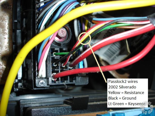 ------------- Soldering is fun!
Posted By: boricua bob
Date Posted: April 27, 2014 at 2:14 PM
Yep thats it. If you use the 556LW bypass the only wire u would have to use is the yellow one for the resistance.
Posted By: frankp05
Date Posted: April 29, 2014 at 2:16 AM
Hello kreg357,
I just have a quick question. Is it necessary to wire that extra relay for the brown acc wire? If so what purpose does that serve. Im planning on going with a similar setup except im using the Viper 5706 on my 00' Suburban but using the 451m and a couple 4 window roll up and down modules. I installed an Avital on my 04' Colorado I forget the model but its just a keyless and rs and that project went pretty smooth but I didnt need any extra relays or anything like I do for my Suburban.
Posted By: kreg357
Date Posted: April 29, 2014 at 4:11 AM
Not exactly sure which vehicle circuits are powered by the Brown ACC2 wire. Sometimes it varies by model and year. While it may not be necessary, for the extra $5 ( relay, harness, fuseholder & fuse ), I would do it, especially if you are adding window roll-ups and other features. Whenever possible, I like to duplicate everything an actual key start does.
-------------
Soldering is fun!
Posted By: frankp05
Date Posted: April 30, 2014 at 1:26 AM
Hey Kreg357
Thanks for the quick reply and the advice, I just have a couple questions one being do I need a relay to wire up my dome light supervision. According to the Viper wiring connections my dome light is a (-) 200mA and my Suburban has a (-) polarity and two different wires both in the BCM. So would I just need to pick one wire to tap it to both? Last but probably not the least haha, which wire am I connecting to the OBD2 violet wire? Is that wire gonna be from the Bypass or the Viper? ....THANKS!!
Posted By: kreg357
Date Posted: May 04, 2014 at 2:47 AM
Not sure if you need Domelight Supervision on that vehicle. Usually, if the dome light comes on with an Unlock from the Factory remotes, it will with the aftermarket system. The two wires mentioned in the wire listing are Dome light and Puddle Lamps. If you have the puddle lights and want them to come on too, you can split the R/S's Domelight output with two 1N4001 diodes and connect to both. I don't believe a relay will be needed.
As for the Violet J1850 Data wire at Pin 2 of the OBD2 connector, that would be used by the bypass module. Remember that only some bypass modules use that wire. Other bypass modules connect directly to the Passlock2 wires. All depends on the bypass module you select for this install.
-------------
Soldering is fun!
Posted By: frankp05
Date Posted: May 04, 2014 at 3:43 PM
Thanks a bunch kreg357!!! I finished installing everything yesterday and it all works great the only issue i have is the radio won't turn off after I remote shutdown the car. Any input?? I didn't connect the re-arm factory wire to the viper, could that be why?
Posted By: kreg357
Date Posted: May 04, 2014 at 5:34 PM
Could be a few things.
Does the radio go off if a door is opened?
How long did you give it to turn off? Most newer vehicles will shut everything down automatically in 10 or 15 minutes.
Did you power the ACC2 circuit? Verify that the external relay is wired correctly and not supplying power all the time.
Might need to add a RAP shutdown with the Viper. This is usually done via the Viper Arm output to a Door Pin. Makes the vehicle think a door was opened. However doing this with an alarm system could confuse the Viper.
-------------
Soldering is fun!
Posted By: frankp05
Date Posted: May 04, 2014 at 8:28 PM
Yes the radio turns off when you open a door and I didn't check to see how long it took before it powered off. I didn't power the ACC2 wire but only because it got late on me and I didn't feel like going out to get one but I'll try it. It's only not turning it off if I remote start then remote shut down the vehicle
Posted By: kreg357
Date Posted: May 04, 2014 at 8:52 PM
Probably needs RAP shutdown if it doesn't happen automatically.
-------------
Soldering is fun!
Posted By: frankp05
Date Posted: May 05, 2014 at 10:25 PM
I really appreciate all your help kreg357, but there is one last problem I am having. My dome lights and puddle lights are not turning on when I arm/disarm the Viper the way it does with the factory fob.
Posted By: wickedhawk89
Date Posted: May 05, 2014 at 11:15 PM
I just partly installed an Avital 5303 r/s with a dball2 connected via D2D. I Connected the blue and green (-) unlock/lock from the avital directly to the blue and green dball2. The starter kill and remote lock and unlock work with no issues. im having an issue with the remote start. it cranks but doesnt start. Do I HAVE to use the hood pin with this setup? also do i have to use the relay setup you did? i actually cut the yellow cable and connected the heavy gauge purple to the starter side and the green to the key side. orange is going to the orange accessory, pink to pink ignition and pink/white to white. I did not use the relay satellite 4-pin connector. do i need to do what you did and install a relay? im not sure what im missing other than the relay and the hood pin switch. 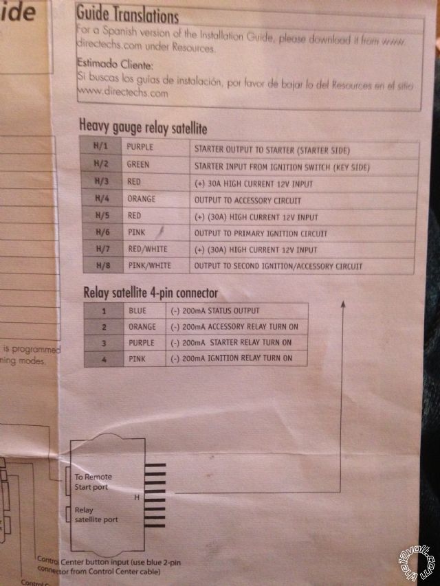 ------------- 2001 GMC SIERRA Z71
Posted By: kreg357
Date Posted: May 06, 2014 at 6:42 AM
This will probably get real confusing with two sessions going on. ( Might be best to start new posts in the regular Car Security and Convenience section and reference this Pictorial. ) Unfortunately, the Pictorial is pretty basic and somewhat generic showing only one specific brand of R/S and bypass module. To cover every brand and model of R/S and R/S w/alarm plus all of the bypass modules would be next to impossible.
FrankP05 - Not sure if I understand the question. Dome light does not come on at all with the Vper Unlock or Dome Light comes on with Viper Unlock but isn't the same as a Factory FOB Unlock ( too long/short, no fade, etc )? You could verify the correct wires by testing with a straight chassis ground via jumper wire. Not sure on a Viper its' Dome Light output specs and characteristics. Perhaps a relay is required if driving both Suburban wires.
WickerHawk89 - The extra relay ( or lack thereof ) and the Brown ACC2 wire isn't causing your no start issue. It sounds like the Passlock2 bypass portion of the DBALL2 is not correct. While the Pictorial used a Data Style Passlock2 bypass module that only needed a single connection to Pin 2 of the OBD2 plug, your DBALL2 requires a connection to the actual Yellow Passlock2 resistance wire. Verify that the correct two wires from the DBALL2 ( Violet/Green & Violet/Brown ) go to the correct Yellow Passlock2 wire in the truck ( earlier in this Pictorial a way to test the Yellow Passlock2 wire was mentioned ). This wiring is shown in the DBALL2 GM5 Type 4 diagram. All these connections should be well soldered. Did the DBALL2 programming go exactly as detailed, especially Step 5? Did the Viper Tach Learn work OK? Also make sure H3, H5 and H7 are all connected to a suitable +12V constant power source ( the trucks Red and RED / White wires ).
No hood pin is required but it really is a great / important safety feature. The Viper kit includes the hood pin switch and firewall pass-through is easily found. If you don't want to drill a hole for the hood pin, you can fabricate a mounting bracket or use a tilt switch mounted to the hood at the hinge. As long as the Viper Hood Pin wire is not grounded, the Viper will try to remote start.
-------------
Soldering is fun!
Posted By: wickedhawk89
Date Posted: May 06, 2014 at 1:16 PM
for some reason i cant get the dball2 to learn the passlock 2 . do you think a permanent passlock over ride would help? ive done everything, by checking and rechecking the connections. when i go to the program steps in the gm5 type 4 it doesnt flash green like it says. it gos green then goes off. im ready to blow up this install.
-------------
2001 GMC SIERRA Z71
Posted By: frankp05
Date Posted: May 07, 2014 at 2:50 AM
To not make it any more confusing for you kreg357 this is my last post haha...when I use the factory FOB either to lock or unlock the vehicle the dome lights and puddle lights turn on but they do not do this function when I use the Viper FOB. Which wire from the viper would I need to connect to those circuits and how?
Posted By: kreg357
Date Posted: May 08, 2014 at 9:27 AM
Frank - PM sent
------------- Soldering is fun!
Posted By: kreg357
Date Posted: May 08, 2014 at 8:10 PM
WickerHawk89 :
Do you have the XKLoader2 cable to verify that the DBALL2 is flashed with the 402.GM5 v3.05 firmware? That would be my first check. Might even re-flash the DBALL2 to be sure.
I am not a DBALL2 user, but perhaps doing the Module Reset or even the Hard Reset and then Vehicle Programing would help.
Of course a total, hard, permanent Passlock2 bypass would be a viable work around but then the normal Passlock2 engine immobilizer function would be gone. You could even do the "relays and resistor" method of Passlock2 bypass controlled by the R/S's GWR output, too. Here is a link : https://documents.audiovox.com/700054.pdf Then the DBALL2 would not need its' connection to the Yellow Passlock2 wire. ------------- Soldering is fun!
Posted By: jdbrumsey
Date Posted: December 01, 2014 at 10:16 AM
I'm having the same problem as WickerHawk89 in that my remote start will crank but not start. I installed everything exactly as in your description with no extras. The Avital returns a code of "low or no RPM", I am using the wire on the gauge cluster for the tack signal. Any thoughts on what else might be wrong?
Thanks for the help!
Posted By: kreg357
Date Posted: December 01, 2014 at 4:05 PM
What are you using for the bypass module? Crank and no start with Passlock2 could be the bypass module.
-------------
Soldering is fun!
Posted By: jdbrumsey
Date Posted: December 01, 2014 at 5:50 PM
iDatalink Data Immobilizer Override for GM Theft Deterrent Systems ADS-TBSL-PL
I Tried to copy your installation to the letter.
Posted By: kreg357
Date Posted: December 01, 2014 at 6:21 PM
I didn't go into detail on the ADS TBSL PL bypass module. They are great units and make the install a breeze, however there are a few steps that you need to do during install.
1. On Page 17 of the install guide, you must do the Installation Mode Selection. You want to get the LED to do the double green blink pattern and then lock it in. This tells the bypass module that you are wired in the W2W mode.
2. Part 2 of the programming process is shown on Page 18 for your Type 6 install. Remember to hold the key in the START position until the LED turns Green for 2 seconds.
I think I would do the Factory Reset procedure ( Page 19 ) first to get everything back to ground zero and then continue on with the 2 steps listed above. Make sure that the ADS TBSL PL responds exactly as per the guide during this whole process.
There are some Avital 4103 programming options that need to be changed.
Menu 1, Feature 1 to Opt 2, if you want the horn confirmation beeps.
Menu 2, Feature 1 to Opt 4, for Tach Mode.
All the other options are OK at their Default setting. Remember to do the Tach Learn process. I usually warm up the engine first so I get a normal idle RPM. ------------- Soldering is fun!
Posted By: jdbrumsey
Date Posted: December 02, 2014 at 11:40 AM
Thanks a lot for your help! That was the issue. It works like a champ now.
Btw, I notice that you didn't use the defog feature, is there a way to implement that on this install? Just Curious, Thanks again!
Posted By: kreg357
Date Posted: December 02, 2014 at 6:25 PM
Sorry, I don't have any info on the Rear Defrost wire. Think it's a pretty rare option, solid rear glass w/defroster. You could try to trace it back from the window. Worst case, a high power, 5 wire relay setup controlled by a latched 2nd Status /Defog output from the 4103.
Another update. The Intrepid has a (+) Multiplexed one wire door lock system. The correct 451M diagram to use is the Type G diagram. I incorrectly mentioned the Type H diagram in an earlier post, sorry. ------------- Soldering is fun!
Posted By: turbotalon1g
Date Posted: December 07, 2014 at 6:46 PM
Would this be the same for a 2003 tahoe? I'm installing a viper 5706v soon with dball2
Posted By: kreg357
Date Posted: December 07, 2014 at 7:07 PM
There are some changes between the 2002 and the 2003 models. There is a Pictorial on the Tahoe's sister vehicle, the Yukon and it's a 2003 model. This vehicle would be very similar to your 2003 Tahoe. Here is a link : https://www.the12volt.com/installbay/forum_posts.asp?tid=133000 ------------- Soldering is fun!
Posted By: mcbride66
Date Posted: January 16, 2015 at 1:52 PM
Is there any chance you could post a step by step wiring guide for Viper 5806v with dBall2.....451M and 8617 Relay?
2002 Chevy Silverado 1500 LT ext. cab
Best Buy installed a 4806v and it never worked correctly. I made them remove everything after the 3rd trip.
Thanks
-------------
mcbride66
Posted By: kreg357
Date Posted: January 16, 2015 at 5:04 PM
2002 Silverado with Viper 5806 and DB-ALL2 flashed with 4.02 GM5 Ver 3.12.106a firmware.
Assumptions : Gasoline engine, factory door locks, going with D2D between Viper & DB-ALL2.
There is no need for the 451M door lock module, the DB-ALL2 will handle the locks and alarm via it's connection to the J1850
Data wire at the OBD2 connector.
Pin Color Description Destination
MH 1 Red (+)12VDC Constant Input Red (+) @ ignition harness
MH 2 Black (-) Chassis Ground Chassis Ground
MH 3 Brown (+) Siren Output Viper siren
MH 4 WHITE/ Brown Parking light isolation Not Used
MH 5 White Parking light output BCM Gray Connector, Brown wire, pin 6 (+) * Set jumper to (+)
MH 6 Orange (-)500mA Ground when armed Not used
DL 1 Blue (-)500mA Unlock output Not used - handled via D2D
DL 2 EMPTY
DL 3 Green (-)500mA Lock output Not used - handled via D2D
RS 1 NC
RS 2 RED / Black (+) Fused 12V acc/start input RED / White (+) @ ignition harness
RS 3 Pink/Black (+) Flex relay input 87a key side Not used
RS 4 Pink/White (+) Ignition 2/flex relay output White (+) @ ignition harness
RS 5 Red (+) Fused 12V Ignition 1 Input Red (+) @ ignition harness
RS 6 Green (+) Starter Input (key side) Yellow (+) @ ignition harness cut wire
RS 7 Violet (+)Start output (car side) Yellow (+) @ ignition harness cut wire
RS 8 Orange (+) Accessory output Orange (+) @ ignition harness
RS 9 RED / White (+) Fused 12V Ignition 2 RED / White (+) @ ignition harness
RS 10 Pink (+) Ignition 1 Input/output Pink (+) @ ignition harness
AST 1 Pink/White (-) 200mA Ignition 2/flex Output not used
AST 2 Blue/White (-) 200mA 2nd Status/rear defog output not used
AST 3 RED / White (-) 200mA trunk release output not used
AST 4 BLACK / YELLOW (-) 200mA dome light output not used
AST 5 Dark Blue (-) 200mA status output Not used - handled via D2D
AST 6 WHITE/ Black (-) 200mA AUX 3 output not used
AST 7 WHITE/ Violet (-) 200mA AUX 1 output not used
AST 8 ORANGE / Black (-) 200mA AUX 4 output not used
AST 9 Gray (-) Hood pin input (NC or NO) to kit supplied hood pin
AST 10 Blue (-) trunk pin/instant trigger input (NC or NO) not used
AST 11 WHITE/ Blue Activation Input not used
AST 12 Violet/White Tachometer input Not used - handled via D2D
AST 13 BLACK/ White (-) neutral safety/parking brake input Not used - handled via D2D ( E-Brake ? )
AST 14 GREEN/ Black (-) 200mA Factory alarm disarm output Not used - handled via D2D
AST 15 Green (-) Door input Not used - handled via D2D
AST 16 BROWN / Black (-) 200mA horn honk output optional ( already have Viper siren )
AST 17 Pink (-) 200mA Ignition 1 output not used
AST 18 Violet (+) Door input not used
AST 19 Violet/Black (-) 200mA AUX 2 output not used
AST 20 Brown (+) Brake shutdown input White (+) @ brake pedal switch
AST 21 Violet / YELLOW (-) 200mA starter output not used
AST 22 Gray/Black (-) Diesel wait to start input not used
AST 23 Orange (-) 200mA accessory output to extra relay Pin 85 ( for Brown ACC2 wire )
AST 24 GREEN / WHITE (-) 200mA factory alarm arm output Not used - handled via D2D
DB-ALL2
D2D harness to Viper
Blue 14 Pin Plug
Pin 2 Violet / YELLOW to OBD2 Pin 2 Violet
Red 12 Pin Plug
Pin 1 BLACK/ White to Tan (-) @ BCM, purple plug, pin B4
Pins 8 & 9 to Yellow Passlock2 wire at steering column harness
Black 10 Pin Plug
Pin 8 Violet to Viper RS Pin 7 thick Violet (+) Start output
Pin 9 Pink to Viper RS Pin 10 thick Pink (+) Ignition 1 Input/output
Extra relay ( 8617 ) for ACC2 :
Pin 85 to Viper AST Pin 23 Orange (-) 200mA accessory output
Pin 86 and 87 to Red (+) @ ignition harness through 25 amp fuse
Pin 30 to Brown ACC2 @ ignition harness
Pin 87a not used
The DB-ALL2 must be flashed with the above specified firmware. Here is a link to the install guide :
https://www.xpresskit.com/DocumentDownload.aspx?documentid=9294&productid=553&firmwareid=6501
Follow the Type 4 diagram / instructions. You will need an XKLoader2 cable to flash the DB-ALL2.
There will be some programming changes necessary for the Viper. Things like Transmission Type, Engine Checking,
etc.
Preemptive excuses : Viper is not one of my normal brands. I have never used a DB-ALL2 bypass module. ------------- Soldering is fun!
Posted By: mcbride66
Date Posted: January 16, 2015 at 7:46 PM
Thank You so much for the quick response. I didn't realize the dball 2 would handle vehicles with positive door locks without the 451M. Perhaps that was the problem with the best buy install. The guy had the 451m as part of the system with nothing but problems including unlocking the doors during remote start for 10 seconds before relocking. I really appreciate the info.
-------------
mcbride66
Posted By: mcbride66
Date Posted: January 17, 2015 at 10:41 PM
I have one more question. Can you please tell me if I need any type of resistor for this setup? I'm going to try install Monday and I just want to make sure I haven't missed anything. Wish I could find someone in my area for professional install. After the Best Buy nightmare I decided to try it myself. Looking over my vehicle wiring I can't see any sign that the installer cut into the Passlock 2 yellow wire. Perhaps that's the reason the factory alarm kept activating upon remote start. Anyway thanks again for all your help
-------------
mcbride66
Posted By: kreg357
Date Posted: January 18, 2015 at 4:21 AM
No extra resistors necessary.
The Passlock2 system and the Factory Alarm system are two separate systems. The Passlock2 not being bypassed correctly
shouldn't cause the Factory Alarm to trigger. There are several places where the installer could tag the Yellow Passlock2 wire.
Personally, I prefer to use a data style Passlock2 only bypass module, not a fully featured bypass module on those trucks and
then hardwire the rest. As the Pictorial shows, a 451M wired to the door locks and the R/S directly controlling the Disarm wire
is the most straight forward way to do it. It would appear that the DB-ALL2 should handle the trucks' Factory Alarm with it's
Smart OEM Alarm Control. There are some DB-ALL2 programming options for that and the Viper has options for Safelock,
too. Worst case scenario, you could connect the Vipers' Disarm Output wire to the trucks' Light Green Disarm wire @ the BCM,
as shown in the Pictorial. ------------- Soldering is fun!
Posted By: mcbride66
Date Posted: January 20, 2015 at 11:42 AM
I'm going to try the setup you posted with dball2 first. Flash firmware 402.GM5 3.05 published was my only programming choice. If dball2 doesn't handle the (+) door locks without 451m & control the factory alarm correctly, then I will try your suggestion for Passlock2 only bypass module.
Q: Yellow Starter1 wire @ ignition harness is the correct one to cut?
(BB installer stripped an opening for connection but didn't cut the wire) The thick yellow wire @ ignition harness is untouched and I would like to know what it's for. Since the passlock2 wire is also yellow I'm going to trace it from ignition switch just to be safe. Thanks........2002 Chevy Silverado LT
-------------
mcbride66
Posted By: kreg357
Date Posted: January 20, 2015 at 5:23 PM
The Starter wire is pictured on Page 1. It is similar in gauge to the White IGN2 wire, not as thick as the Pink, Orange or Brown wires.
But definitely thicker than the Yellow Passlock2 wire and it originates from a different connector. Think there is a picture of the Passlock2
wires later in the Pictorial ( Page 2 ). It should be real easy to distinguish between them visually but using a DMM will be very definitive, too.
The Yellow Starter wire does not have to be cut if you don't want the Starter Kill / Anti-Grind features. Just connect the Viper Violet directly
to it and don't use the Viper Green wire. ------------- Soldering is fun!
Posted By: mcbride66
Date Posted: January 22, 2015 at 7:27 PM
Took me all day but I have the 5806 & dball2 in place. I have triple checked everything just to make sure before I complete the hookup. I pretty much understand everything except the relay 8617. Can you please tell me why 86 & 87 requires +12 volt hookup? Thanks
2002 Chevy Silverado
-------------
mcbride66
Posted By: kreg357
Date Posted: January 23, 2015 at 8:34 AM
The relay is basically a switch. In your case, the +12V applied to Pin 87 goes nowhere until the relay's coil is energized. Once the coil
is energized, Pin 87 is internally connected to Pin 30 and the 12V signal on Pin 87 is output to the vehicle on Pin 30.
The relay's coil has two pins. By convention, Pin 85 receives a negative input and Pin 86 receives a (+) input. For your application, we
applied a +12V constant signal on Pin 86. When the Viper outputs a (-) Accessory Output to Pin 85, the relays coil energizes.
Being as Pin 86 and 87 need the same +12V signal, we joined them together. There is a pretty good section on Relays on this site. ------------- Soldering is fun!
Posted By: mcbride66
Date Posted: January 28, 2015 at 11:29 AM
I just wanted to say thank you for all your help. Everything works ok except the OEM Alarm. Shutdown after remote start triggers the factory alarm. If I change to safelock it won't trigger the alarm but the doors unlock during remote start and relock after truck has cranked. Gonna try the (-) 200mA factory alarm disarm output to light green disarm wire on truck. It's a straight hookup without any resistors or relay right?
Thanks again, Ray
2002 Chevy Silverado
-------------
mcbride66
Posted By: kreg357
Date Posted: January 28, 2015 at 11:43 AM
Yes, direct connection from the Viper Factory Alarm Disarm Output to the trucks' Light Green Disarm wire @ BCM.
-------------
Soldering is fun!
Posted By: mcbride66
Date Posted: January 28, 2015 at 3:37 PM
Now it's time for you to yell at me. Lol. I have been trying different settings with the bit writer and I decided to zap to restore default features not realizing it would remove my remotes from memory. Now I can't get 5806 to pair the remotes. Bit writer shows 0 transmitters and refuses to allow change in programming. I tried everything I found in paperwork to pair remotes. Please help
-------------
mcbride66
Posted By: kreg357
Date Posted: January 28, 2015 at 4:22 PM
Oh, oh. Remember my preemptive excuse? Not a big Viper user. There are BitWriter only options that locks out any programming changes and remote additions. Perhaps the experts from across the Atlantic or up north can lend a hand.
-------------
Soldering is fun!
Posted By: mcbride66
Date Posted: January 29, 2015 at 12:08 PM
Trying to get valet/control button to go into programming mode. The bitwriter shows programming mode unlocked, however the control will only go in and out of valet mode. Blue Light steady on or off. No flashing or chirps. If anyone knows how to get into programming mode with control button for viper 5806v will you please let me know. I have tried all instructions with no success. Trying to get 2 remotes re-paired with unit after zapping with bitwriter.
Any info is greatly appreciated.
Thanks
2002 Chevy Silverado
-------------
mcbride66
Posted By: mcbride66
Date Posted: January 30, 2015 at 2:05 PM
Fixed my issue. Had to run (-) Door Input from Viper unit. Could not get Dball2 to handle (-) Door Input via data alone. Was able to program in remotes using control button afterwards. Also hooked up factory disarm wire and everything works as it should. I could not have done this without you. I'm down to the last thing, the passenger door trigger. How do I hook that up? The reason I ask is I have setting for auto relock (after unlocking via remote) unless door is opened within 30 seconds. Passenger door does not work when opened. It continues to count down before relocking. Drive door works as it should. Thanks again, Ray
-------------
mcbride66
Posted By: ycavada01
Date Posted: June 02, 2015 at 4:00 PM
Can you tell me how to doit with a relay because i have a alarm system in my sierra 99 and have a relay in it, and i will like to know if I can use it or not
Posted By: brandie928
Date Posted: June 07, 2015 at 10:39 AM
I have a huge favor to ask anyone on this form about wiring a Avial 3100 XL to my 99 silverado 1500. i bought this alarm with the impression that my now ex boyfriend was going to help install it. well point being he is no longer in the picture and i no longer have instructions to hook the system up (not that i am a big expert on auto wiring) . So if anyone could help with the most detailed instructions, kind of like paint by numbers sort a speak. plus the pictures like in this form would be the greatest thing ever. I have the door actuators already installed but not wired to anything and that is as far as i got. im not sure what other information i need to say to get help. so i will leave it at that. thank you very much for your time.
Posted By: kreg357
Date Posted: June 07, 2015 at 5:11 PM
Going to need some more info to assist you. In the mean time I have uploaded the Avital 3100 L Install Guide to the Downloads Section. It is not the 3100 XL install guide but should be close. Here is a link : https://www.the12volt.com/installbay/file.asp?ID=1334
A couple of ideas. You mentioned adding door actuators. Does that mean your truck did not come from the factory with power locks? Usually adding power locks to a vehicle includes a kit with a power lock controller. If that is the case, it will simplify the Avital 3100 install. If it was just the lock solenoids and mechanical connection to the vehicle inside the door, with 2 or 5 wires hanging free, you will need more parts and time to do the install.
My suggestion would be to start a new thread in the Car Security and Convenience Section. Include all the info about your truck, ie :
1999 Chevrolet Silverado 2 door with no factory power locks or factory alarm. After-market door lock solenoids installed, both 2 wire with no controller. Looking to install an Avital 3100 XL alarm system. I love to solder and have to tools and know how to take the lower dash panel off. Here is a link to the Avital Alarm system xxx and here is a link to the Pictorial I'm going to use as a reference, etc, etc, etc Here is the pin out for the Avital 3100 and my proposed vehicle connection points :
H1/1 ORANGE (-) 500 mA GROUND-WHEN-ARMED OUTPUT
H1/2 WHITE (+/-) SELECTABLE LIGHT FLASH OUTPUT
H1/3 WHITE/ BLUE (-) 200 mA CHANNEL 3 VALIDITY OUTPUT
H1/4 BLACK/ WHITE (-) 200 mA INTERIOR LIGHT ILLUMINATION OUTPUT
H1/5 GREEN (-) DOOR TRIGGER INPUT, ZONE 3
H1/6 BLUE (-) MULTIPLEX TRIGGER INPUT, ZONE 1
H1/7 VIOLET (+) DOOR TRIGGER INPUT, ZONE 3
H1/8 BLACK (-) CHASSIS GROUND INPUT
H1/9 YELLOW (+) IGNITION INPUT, ZONE 5
H1/10 BROWN (+) SIREN OUTPUT
H1/11 RED (+)12V CONSTANT POWER INPUT
H1/12 RED / WHITE (-) 200 mA CHANNEL 2 VALIDITY OUTPUT
H2/1 GREEN (-) LOCK, (+) UNLOCK OUTPUT
H2/2
H2/3 BLUE (+) LOCK, (-) UNLOCK OUTPUT
H3/1 Black Starter In
H3/2 Black Starter Out
That should start the ball rolling. ------------- Soldering is fun!
Posted By: brandie928
Date Posted: June 09, 2015 at 4:50 AM
Thank you very much for your help. The info given was perfect.
again much thanks
brandie
Posted By: super dave426
Date Posted: December 27, 2015 at 1:35 PM
I wanted to thank you for the detailed post and let you know I installed these exact products in my 2001 GMC Sierra with the Factory Alarm and remote locks yesterday. It seems overwhelming at first, but reading through this thread a few times and then pre-wiring and soldering all wires that tie together before made it even easier, I even cut off the wires that weren't needed to make it less confusing. There are 2 things that I learned that I felt I would share, first there is a jumper that comes taped to the Avital that you set for the light flash, if you want it and second your instructions below must be followed in order for the bypass to work. This is the first RS I have ever attempted and it was much easier than expected, thanks again for sharing! It was nice that Amazon had the Avital for $42 (I got all the parts needed there).
kreg357 wrote:
I didn't go into detail on the ADS TBSL PL bypass module. They are great units and make the install a breeze, however
there are a few steps that you need to do during install.
1. On Page 17 of the install guide, you must do the Installation Mode Selection. You want to get the LED to do the
double green blink pattern and then lock it in. This tells the bypass module that you are wired in the W2W mode.
2. Part 2 of the programming process is shown on Page 18 for your Type 6 install. Remember to hold the key in the
START position until the LED turns Green for 2 seconds.
I think I would do the Factory Reset procedure ( Page 19 ) first to get everything back to ground zero and then continue
on with the 2 steps listed above. Make sure that the ADS TBSL PL responds exactly as per the guide during this whole process.
There are some Avital 4103 programming options that need to be changed.
Menu 1, Feature 1 to Opt 2, if you want the horn confirmation beeps.
Menu 2, Feature 1 to Opt 4, for Tach Mode.
All the other options are OK at their Default setting. Remember to do the Tach Learn process. I usually warm up the
engine first so I get a normal idle RPM.
------------- Dave
Posted By: super dave426
Date Posted: December 27, 2015 at 4:16 PM
Just wanted to add that I found it a little confusing that in the 6 heavy gauge harness (10 Gauge)you tie into the Ignition and Starter wires in the ignition harness and those 2 wires appear to be 16 Gauge, just doesn't seem to match up, but it worked. Looking at the lone yellow wire that just crosses through the entire area made me wonder if that was supposed to be used because of the heavy gauge, so I searched around and found out that it's most likely the Air Bag, good thing I didn't tap it.
-------------
Dave
Posted By: kreg357
Date Posted: December 28, 2015 at 9:25 PM
Always be careful with yellow plugs and wires. In this case, that is a yellow sleeve over several airbag wires.
It's becoming common to find wires of difference gauges in the main ignition connector, like this 2011 RAV4 :
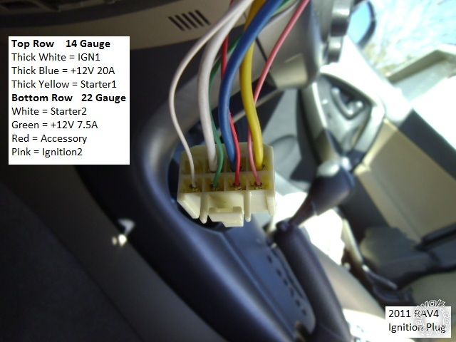
------------- Soldering is fun!
Posted By: zlem
Date Posted: September 10, 2016 at 6:48 PM
I have a 1999 silverado and followed this write up to attempt to install a remote start. I went through the brief instructions that came with the unit and hooked everything up according to this write up. Audiovox model# AS-9055T is the remote start I picked up, didn't need anything with keyless entry or security since my truck is not equipped with either. I hooked everything up, tried to program tach rate which I don't know if it was successful, and programmed my remote. The truck fired with the click of the remote and then shut off after a second and the starter continued to crank until I pressed the brake. Any ideas?
Posted By: lurch228
Date Posted: September 10, 2016 at 7:20 PM
No keyless or Oem Security doesn't mean no passlock ie VATS which needs a bypass type install. Using the included resistors with the unit as per the VATS instructions. Key cylinder Wires should be small diameter that are White and WHITE/ Black Or WHITE/ Blue and WHITE/ Yellow. Using a relay and matching resistor to the VATS wire #1 (White or WHITE/ Blue). Following the VATS instructions in the Audiovox manual. Resistor is now part of the key cylinder its self instead of being in the key as the manual lists.
You need to check you wiring to starter as it shouldn't continue to crank for more that a few seconds unless you have a bad unit or the wrong wire connected to the starter. Seen one other Audiovox that cranked until you pressed the brake but this years ago.
Disconnect the yellow R/S wire from vehicle and the use a DMM to test it by hitting the R/S, with one test probe to ground and verify that it times out.
Posted By: kreg357
Date Posted: September 10, 2016 at 8:12 PM
As Lurch says, you need a Passlock2 bypass. You can achieve this a few ways. If you have a Digital Multi Meter,
various resistors and a relay or two, you can do it following DEI Tech Tip 1048. Here is a link to this document :
https://www.the12volt.com/installbay/file.asp?ID=1206
If you want to save some time and trouble, get a Passlock2 bypass module. My suggestion would be an iDatalink
ADS TB GM, ADS TBSL GM or ADS TBSL PL. All come pre-loaded with the correct firmware and are extremely reliable.
Another decent choice would be the Fortin PASSLOCK-SL2-V2.
It's possible your over-crank condition is due to the Tach learn.
-------------
Soldering is fun!
Posted By: zlem
Date Posted: September 10, 2016 at 11:16 PM
Thank you for the quick responses. This is my first install and wasn't aware that the vats bypass needed to be used. I will try the bypass tomorrow and follow the diagram in the manual. Thanks for the assistance
Posted By: lurch228
Date Posted: September 11, 2016 at 2:11 PM
You will only cut the one VATS wire #1 (White or WHITE/ Blue) to go thru relay and connect to the other. Test the lock cylinder resistance and match it for the relay to goto the #2 WHITE/ Black OR WHITE/ Yellow.
Posted By: zlem
Date Posted: September 11, 2016 at 5:34 PM
OK so I found 5 wires that go up towards the key cylinder. A group of 3 that go towards the topside of the cylinder (RED / white, ORANGE / black, and yellow), and the group of two which go towards the back of the cylinder (brown and green). I cut the yellow wire in the group of 3 and stripped the ORANGE / black and get no resistance when the key is off or in the on position. I tried from the cut yellow to the RED / white and had a resistance around 6k when key was off and nothing when the key is turned on. Also the truck would not start at all when the yellow wire was cut. Am I looking at the right wires? Why will my key not show a resistance so I can match a resistor?
Posted By: zlem
Date Posted: September 11, 2016 at 5:57 PM
Posted By: pts760
Date Posted: September 11, 2016 at 7:03 PM
Your key wont show a resistance because you don't have a VATS system like you have been told. You have a Passlock 2 system and your resistance has to be tested from the yellow wire from the group of three passlock wires.
these are your wires: RED / white (12v), Yellow ( R-code or Resistance), ORANGE / Black (Passlock ground). You will only use yellow and ORANGE / black. Here's a link on how to bypass it (Refer to method one for wiring): Directed Tech Doc 1048------------- I drink current, eat ohms, and bleed voltage
Posted By: zlem
Date Posted: September 11, 2016 at 8:39 PM
Where does the status wire- come off of that goes to pin 85 from the method 1 diagram?
Posted By: kreg357
Date Posted: September 11, 2016 at 9:16 PM
Could be called GWR, Ground When Running, Status Out, 3rd Ignition, etc. Most R/S control units have this bypass module control signal.
-------------
Soldering is fun!
Posted By: zlem
Date Posted: September 12, 2016 at 7:24 PM
Well I tried the bypass and still no luck. Could it be something to do with the tach wire? As soon as I follow the instructions to recognize the tach rate, I turn the key and the truck starts, then shut the truck off and try the remote. The truck fires but doesn't start and then the starter finally times out. When I try to start with the key it won't start either.
Posted By: pts760
Date Posted: September 12, 2016 at 7:51 PM
You probably locked out the Passlock 2 system. Does your security light flash or stay on when you crank it with the key?
In order to get out of the Passlock 2 lockout (grab a trickle charger or jump pack) you have to:
1.) Key On/Ignition ON 10 minutes
2.) Key off 3 sec
3.) Key ON/IGnition ON 10 minutes
4.) Key off 3 sec
5.) Key On/Ignition ON 10 mintues (Secuirty light on dash should be off now)
6.) Key off 3 sec
7.) Start vehicle with key
This should allow you to start the truck with your ignition key. If it doesnt than your passlock wiring is wrong and/or the R-code value is incorrect. You can always buy a bypass module to take care of the passlock 2 also. Its a lot easier for a beginner to Passlock 2
-------------
I drink current, eat ohms, and bleed voltage
Posted By: zlem
Date Posted: September 12, 2016 at 8:54 PM
I went back out and the truck started right up with the key, tried the remote start again and it didn't start like before, then the truck wouldn't start with the key again. I don't see any security lights, would there even be one if it isn't equipped with a security system? When I measured my resistance on my yellow wire I got 678 ohms, so I matched my closest resistor which was 680 ohms. I got the r/s unopened for free and was hoping to learn something without buying a bypass module.
I have my resistor coming off of my ORANGE / black wire to pin 87, yellow wire from bcm to pin 30, yellow from key cylinder to 87a, 86 going to my ignition 1 wire, and 85 going to ignition 3 out of my 12 pin harness.
Posted By: zlem
Date Posted: September 12, 2016 at 9:30 PM
Where is the best place to buy an iDatalink module for this vehicle?
Posted By: lurch228
Date Posted: September 12, 2016 at 9:56 PM
zlem] wrote:
I went back out and the truck started right up with the key, tried the remote start again and it didn't start like before, then the truck wouldn't start with the key again. I don't see any security lights, would there even be one if it isn't equipped with a security system? When I measured my resistance on my yellow wire I got 678 ohms, so I matched my closest resistor which was 680 ohms. I got the r/s unopened for free and was hoping to learn something without buying a bypass module.
I have my resistor coming off of my ORANGE / black wire to pin 87, yellow wire from bcm to pin 30, yellow from key cylinder to 87a, 86 going to my ignition 1 wire, and 85 going to ignition 3 out of my 12 pin harness.
(+/-) 5% is the norm for resistor match but try to stay at or lower for best results. To allow for any additional resistance the relay and connections might add. As you could be at the max resistance for that tier range. If you measure the resistance of the resistor across the 87 & 30 connections at the vehicle when active it will tell you if you need to go to a lower resistor. Just adding a length of wire can increase the resistance measurement.
Posted By: pts760
Date Posted: September 12, 2016 at 10:02 PM
It is possible that there is no security light. Based on your post previous post your resistor value looks good and your wiring does as well.
One option is that you can eliminate the relay and tie the resistor from ORANGE / black to the BCM side yellow wire. Do the 3 sets of 10 min and the BCM will learn the resistor value (same process when you replace a ignition cylinder in a passlock 2 vehicle).
I do this a lot because passlock 2 systems aren't very reliable as the years go by. The down fall is if something happens to your wiring /resistor then you'll be stranded until you fix the resistor and reset the passlock
Option 2: idatalink bypass (ADS-TB). You can get one at a local shop, bestbuy, eBay, sonixelectronics.com
You don't have to use idatalink either. Just tell a local shop what you are trying to bypass and they can set you up with what you need. If you get a idatalink module, make sure the bypass is flashed with the correct firmware. You can look on idatalinks website and it will give you the wiring diagram for your truck.
-------------
I drink current, eat ohms, and bleed voltage
Posted By: zlem
Date Posted: September 12, 2016 at 10:12 PM
What do you do after the bcm recognizes the new resistor value?
Posted By: pts760
Date Posted: September 12, 2016 at 10:20 PM
Solder the resistor from yellow BCM side to ORANGE / black. Learn the R-code to BCM (3 sets of 10min). Start the vehicle with the key like normal & remote start like normal. Passlock 2 will be completely bypassed after its done
-------------
I drink current, eat ohms, and bleed voltage
Posted By: lurch228
Date Posted: September 12, 2016 at 10:27 PM
The fact that the truck started with the key and not the R/S and then after it wouldn't with the key is a sign that there is a difference between the key cylinder and the relay bypass resistance. Triggering the security to stop the vehicle from starting.
Posted By: lurch228
Date Posted: September 12, 2016 at 10:31 PM
You can disable the key cylinder by putting the resistor between the passlock2 wires and leaving the key cylinder side unhooked. Permanently disabling the key cylinder tamper security.
Posted By: zlem
Date Posted: September 12, 2016 at 10:32 PM
I'll give this a shot later this week. Thanks for your input
Posted By: lurch228
Date Posted: September 12, 2016 at 10:33 PM
No problem.
Posted By: zlem
Date Posted: September 13, 2016 at 7:42 PM
I have the resistor in there now and did the 3 sets of 10. Truck fired right up and then I tried the r/s and it fired up as well. Seems like everything is working except for my starter still won't shut off when the truck fires up. When I test the start wire from the r/s alone it turns on and shuts back off after 2 seconds like it should. As soon as I hook it back up to the starter wire of the truck and hit the r/s, the truck starts and the starter keeps on cranking. I also tested the white tach. wire coming off of the back of the gauge cluster, 10v with key in on position and around 6v when running.
Posted By: pts760
Date Posted: September 13, 2016 at 8:12 PM
How are your connection made? Scotch lock, twist and tape, solder, etc?
-------------
I drink current, eat ohms, and bleed voltage
Posted By: zlem
Date Posted: September 13, 2016 at 8:16 PM
Well I have most everything twist and taped and a couple scotch locks until everything is working properly and then solder.
Posted By: pts760
Date Posted: September 13, 2016 at 8:17 PM
In the feature selection menu do you have 4) mode select, set for Tach and not the default voltage?
-------------
I drink current, eat ohms, and bleed voltage
Posted By: pts760
Date Posted: September 13, 2016 at 8:21 PM
I don't remember if you said or not did you program the tach to the remote start and receive the parking light conformation flashes
-------------
I drink current, eat ohms, and bleed voltage
Posted By: zlem
Date Posted: September 13, 2016 at 8:23 PM
I believe everything is set to default which it says is tach
Posted By: pts760
Date Posted: September 13, 2016 at 8:33 PM
Your right I misread the manual tach is default. Did you get the confirmation flashes when you programmed the tach as the manual indicates. If so try programming the unit for tach sensing just to be certain that option is programmed correctly
-------------
I drink current, eat ohms, and bleed voltage
Posted By: zlem
Date Posted: September 13, 2016 at 9:14 PM
I went out and checked the settings and it indeed showed it was on voltage. It almost seems like my programming button is malfunctioning. I turn the key on, press the button 3 times, shut the key off then back on and press 2 times to enter the selectable features. Then if I want to get to 4-mode select, I push it 4 more times and it will blink 5 or 6 and end up in a different feature.
Posted By: zlem
Date Posted: September 13, 2016 at 9:35 PM
Is there a way to reset everything to default?
Posted By: pts760
Date Posted: September 13, 2016 at 10:50 PM
There may be some type of master reset in the manual. Other than that I haven't installed a lot of audiovox units so regarding the program features and program button you'll have to have someone else chime in on that or call audiovox tech support. I do remember their program button being touch and it took me a few tries to program the feature I wanted. It's really easy to program if you have the RF Programmer but you'll only find that at a dealer unless you wanna blow $50-70 on buying one.
-------------
I drink current, eat ohms, and bleed voltage
Posted By: lurch228
Date Posted: September 13, 2016 at 11:25 PM
zlem] wrote:
I have the resistor in there now and did the 3 sets of 10. Truck fired right up and then I tried the r/s and it fired up as well. Seems like everything is working except for my starter still won't shut off when the truck fires up. When I test the start wire from the r/s alone it turns on and shuts back off after 2 seconds like it should. As soon as I hook it back up to the starter wire of the truck and hit the r/s, the truck starts and the starter keeps on cranking. I also tested the white tach. wire coming off of the back of the gauge cluster, 10v with key in on position and around 6v when running.
Tach voltage should rise when engine rpm goes up, did you test this?
Posted By: zlem
Date Posted: September 14, 2016 at 9:40 PM
Tach voltage did rise when rpm goes up. Seems like the unit won't save my programmable selection. I change it from voltage to tach when startimg and it doesn't save it.
Posted By: lurch228
Date Posted: September 14, 2016 at 9:56 PM
Then reset the unit by deleting all remotes then pull power and reconnect repair the remotes and try again!
Posted By: lurch228
Date Posted: September 14, 2016 at 9:57 PM
zlem] wrote:
Is there a way to reset everything to default?
Not sure with audiovox but wit DEI you can Zap it with Bitwriter.
Posted By: zlem
Date Posted: September 15, 2016 at 2:33 PM
Just curious. How would you make it sense voltage instead of tach rate?
Posted By: lurch228
Date Posted: September 15, 2016 at 3:10 PM
For voltage sense no tach wired is needed to be hooked up. Just change the setting to voltage sense and follow any instructions for it in the installation manual.
Posted By: asb2106
Date Posted: December 22, 2016 at 4:39 PM
I've read through all 10 pages, and I couldnt find anything specific..
Is the 451m module required?
I have done a few of these trucks (its been a few years since my last one) and I dont recall hooking up any door lock modules, just wiring directly from the avital to the fuse panel i think!
I wish i left myself better instructions from before. I guess i could also get under my 99 and figure out what i did there.
Just wondering if anyone could confirm that the lock/unlock will work from 4103LX without the need of the 451m.
Thanks!
-------------
Tony B
The road to success is always under construction. - Lily Tomlin
Posted By: kreg357
Date Posted: December 23, 2016 at 6:04 AM
Most installers get the power door lock wires at the BCM, as shown in the Pictorial and in most common wiring guides found
online. Bulldog Security info shown below :
POWER LOCK LT. BLUE (+) TYPE A @ BCM BROWN PLUG, SEE NOTE #3
POWER UNLOCK WHITE (+) TYPE A @ BCM BROWN PLUG, SEE NOTE #3
NOTE #3: The BCM is located behind the Drivers Side of the dash, the plugs on the BCM face towards the rear of the vehicle.
With your selection, the Avital 4103LX, it only outputs a (-) door lock signal. This (-) signal must be converted to a (+)
signal to satisfy the trucks needs. The 451M is a convenient way to to this. On a side note, your memory might be correct
if you were using certain model R/S units produced 10 years ago. Some units had "alternating lock outputs" that were both a
(-) lock and (+) unlock signal ( and visa-versa ) on the same wire. Units with this type of lock output are no longer made.
-------------
Soldering is fun!
Posted By: asb2106
Date Posted: December 23, 2016 at 8:00 AM
indeed! you just triggered a few more memories with that reply. I remember using relays to produce a + trigger!
Phew, i can get those locally too.
cheers, thanks!
-------------
Tony B
The road to success is always under construction. - Lily Tomlin
Posted By: jlogs95
Date Posted: January 29, 2017 at 5:42 PM
Kreg was trying to see if can get help wit a viper 5607v with xk01 bypass i need help with the 10 pin heavy gauge connector wires i have a 2000 gmc sierra
Posted By: kreg357
Date Posted: January 30, 2017 at 8:15 AM
2000 GMC Sierra with Viper 5706
Remote Start, 10-pin heavy gauge connector
1 NC No Connection
2 RED / BLACK (+) FUSED 12V ACC/STARTER INPUT RED (+) @ IGNITION SWITCH HARNESS
3 PINK/BLACK (+) FLEX RELAY INPUT 87A not used
4 PINK/WHITE (+) IGNITION 2 / FLEX RELAY OUTPUT WHITE (+) @ IGNITION SWITCH HARNESS
5 RED (+) FUSED 12V IGNITION 1 INPUT RED / White (+) @ IGNITION SWITCH HARNESS
6 GREEN (+) STARTER INPUT (KEY SIDE) YELLOW (+) @ IGNITION SWITCH HARNESS \
7 VIOLET (+) STARTER OUTPUT (CAR SIDE) YELLOW (+) @ IGNITION SWITCH HARNESS / cut wire
8 ORANGE (+) ACCESSORY OUTPUT ORANGE (+) @ IGNITION SWITCH HARNESS
9 RED / WHITE (+) FUSED 12V IGNITION 2 RED (+) @ IGNITION SWITCH HARNESS
10 PINK (+) IGNITION 1 INPUT/OUTPUT PINK (+) @ IGNITION SWITCH HARNESS
-------------
Soldering is fun!
Posted By: rheckbert3
Date Posted: April 04, 2017 at 11:46 AM
Hi Kreg357,
This is Rick that installed the ultra start into my 99 F150 following your tutorial a couple of years ago and it's been great!
https://www.the12volt.com/installbay/forum_posts.asp?tid=135434
So least to say I bought a newer truck and I really miss my remote start. I have a 2002 Chevy Silverado 2500 HD. I just purchased everything from Amazon including a hood tilt switch for 89$, (tilt switch, avital 4105L, idatalink Bypass, DEI 451 and relay, harness and fuse+holder) I read through the 11 pages here and have been doing some other research; So I think I'm ready to go! :)
But I would like to say thank you for all your great tutorials and how much help you give when someone gets stuck. Because of that I know I will be able to get help if I encounter any issues with this one ;)
Once I get the remote start working I was thinking of purchaseing a directed DSM250 Smart Start modual. Becuase in this tutorial you are using a W2W connection between the bypass and RS I think I can just connect the smart start modual to the RS using the Datalink 4 pin connection (red connector ESP2/D2D). Then run power and ground to the DSM250. Do you think this is correct?
https://www.manualslib.com/manual/809886/Directed-Electronics-Dsm200-Series.html?page=3
Just not sure if I want to cough up the dough for the smart start as a monthly subscription.
Thank you!
Rick
Posted By: rheckbert3
Date Posted: April 05, 2017 at 9:49 PM
Also another question in addition to above :)
Is there a way for me to activate the heated seat with the remote start based on temperature outside like I read you did in a 03-06 Yukon? Or maybe a push of an aux button on the RS fob?
Posted By: kreg357
Date Posted: April 07, 2017 at 6:55 AM
Hi Rick,
The second one is always easier. That price for the parts is very good. Going W2W between the ADS TBSL PL will
leave the 4105s' DBI D2D port open and available for the DSM250 if you decide to add that later. I'm not a DEI
person, but the last I heard, getting the DSM250 SmartStart activated requires a DEI Dealer. That might have
changed recently so I'm not positive about it.
As for the heated seats, in that GEN truck there are no full featured bypass modules that can directly control them.
I can't find any info one the hearted seat control wiring but it might be possible. Perhaps someone with access
to DirectTech info can check and supply it. The 4105 doesn't have AUX outputs per se. It has a Trunk Release
output but that will also unlock the doors. You could use the 2nd Status / Defrost wire with appropriate programming.
The only tips are about wire routing. The metal knee brace has sharp unfinished edges, so be careful when running
wires in that area. You can file the metal plates edges and apply electric tape in critical areas. You can also
sheath the wires like the Ultra Start does with its' ignition wires or use TESA tape or a similar product to wrap
and protect them.
Good luck with the new truck!
Kreg
-------------
Soldering is fun!
Posted By: rheckbert3
Date Posted: May 14, 2017 at 7:37 PM
Hi Kreg,
The 02 2500 starts up with the push of a button!  I didn't have any major issues. I did not do the DSM250 smart start. I actually found a way to program the smartstart module yourself but I don't know that I want to pay monthly for the subscription. But at some point down the road I could add it with the D2D wire if I want to. I didn't worry about the heated seats. (going to kick myself in the butt come winter!) 
I took care to put wire loom on a lot of harnesses. I also put the loom over the sharp edges of the knee brace where the wires were running past. I couldn't believe how sharp the metal is in up under there.
It took me quite a while but I actually managed to pull a lot of the ignition wires out of their connector to be able to slip heat shrink onto the connection after I soldered every connection. I really like the Avital 4105. Very small and compact. Its a little tricky to program at first trying to count the number of LED flashes until you enable the horn to chirp. But overall its a great little remote start module. The bypass worked great, was simple to install and is very small. The doorlock module made the door locks super easy and I actually really like the mercury hood tilt switch.
The only thing I might change for next time is to prep the bypass and the remote start unit on the bench and cut all the wires to length.
Thank you for all your help as usual!
Ricky
Posted By: kreg357
Date Posted: May 15, 2017 at 8:19 PM
The 4105 is a solid unit and the remotes are very nice. Glad it went smoothly.
I think Ultra Start is the easiest to program with the remotes and got the BitWriter for the DEI systems because they are more difficult. Next time try a Prestige unit like the APS57E from Audiovox. They are even more compact ( half the size of the 4105 ) and have comparable features. Programming them with the remotes is fairly easy.
Good luck with the new truck! ------------- Soldering is fun!
Posted By: wakeboarder
Date Posted: June 11, 2017 at 6:57 AM
Kreg357,
I wanted to add a couple things that I needed to do to complete my 2002 Silverado 2500HD install with the Viper 5806V with the DB-ALL3 flashed with 403GM5 V4.03 firmware. I did these in addition to what you had listed.
Viper 5806V
AST13 BLACK/White (-)neutral safety/parking brake input to blue wire at parking brake switch (Viper would not allow a remote start until this wire is grounded)
AST15 Green (-) door input to Tan(-)@BCM, purple plug, B4, (This allowed programming Viper using the control center button)
Thank you for your post on this topic, it was very helpful.
All,
One issue that I am having is getting the driver priority unlock to work properly.The vehicle is wired per Kreg357's post on the 5th page of this forum with the two exceptions above. Therefore the door locks are handed D2D to the DB-All3. The DB-All3 is communicating the unlock information on the vehicle CAN line. The 1st time I hit the remote's unlock button, it unlocks all four doors. It should just unlock the driver's door. My factory remote still operates with the driver priority unlock.
I have the DB-All3 flashed to use the driver priority setting. Just in case, I ensured the Viper was programed for a single unlock pulse and for the shortest duration lock/unlock pulse.
Could it be a bug with the DB-All3? I was thinking of trying the DB-All2 to see if it would perform better.
Posted By: slade725
Date Posted: September 24, 2017 at 3:14 PM
Where are you all putting the remote start unit? I'm going to install a prestige aps997E, evo-all and an dei 451. I don't know where to put all of this stuff, I may remove the dash and place the 997E there, the 451 in the drivers door and the evo-all under the dash. There doesn't seem like a lot of room under the column.
Posted By: rheckbert3
Date Posted: September 25, 2017 at 9:35 PM
I put my remote start modual on its side tucked between the two vertical metal plates to the left of the steering column. I zip tied the modual to the metal bracket. I zip ties the door lock modual to a dash frame metal piece on the right of the column. Cant quite remeber where I stuffed the bypass unit.
It is a little tight in this area on these trucks. Other people may have a better spot than I placed mine.
One thing to note that Kreg warned of is how sharp the metal brackets and metal plates are. I took 3/8? inch split loom and placed it over the edges of the metal plates and tried to run the wires over the split loom to protect them from being chaffed through.
Posted By: rheckbert3
Date Posted: September 25, 2017 at 10:00 PM
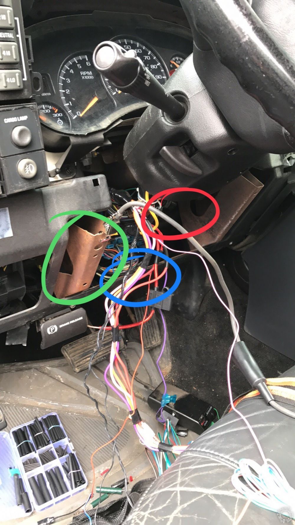
The green circle is where I put the remote start. Zip tied inside the metal bracket brace.
The blue circle is where I put the bypass module. Ziptied to the backside of that metal bar.
The red circle is where I placed the door lock unit. Somewhere up in there.
Posted By: kbenny
Date Posted: October 02, 2017 at 9:29 PM
I followed the instructions and it made the installation of an Avital 4105L, DEI 451M, and Fortin passlock SL2 very easy.
I would like to note one color difference on the parking light + wire on the BCM, mine was light blue and not the brown indicated in the instructions. It was in the same pin location and I checked it with a DMM but just in case anyone else runs into this. (2000 Silverado LT)
I have a question that some of you might be able to help me with:
I want to use the - trunk release option to activate my Rigid LED light bar.
As mine is a truck I don't have a "trunk" to release so I thought I would put it to another use.
The light bar already has a 30a relay providing power to it under the hood.
I am just looking for a way to convert the momentary trunk release - signal from the RS to a constant + signal I can tap into the existing light bar signal wire.
I have looked up the momentary - to constant + latching relay diagram found on this site but wanted to know if there is a single relay available to achieve this or any other way that would be simpler.
Any help is appreciated.
Posted By: kreg357
Date Posted: October 03, 2017 at 7:44 PM
While bulky, I have used that 4 relay momentary to latched relay setup with good results. If the Rigid LED
light bar current draw is less than 10 Amps you could use mini-relays instead of the larger 30/40 Amp Bosch
style relays.
A few questions :
1. What is the current draw of the Rigid LED light bar?
2. How is the 30 Amp manual control relay under the hood triggered ( + or - from switch )?
If the current draw is below 10 Amps you could use this > $3.00 module and a direct connection to the Rigid LED
light bar. ( just one of many listed on EBay )
https://www./itm/1-Channel-Latching-Relay-Module-with-Touch-Bistable-Switch-12V-/272676896637?epid=892013745&hash=item3f7ccf3f7d:g:Ci8AAOSw7QNZlUJ4
If the current draw was over 10 Amps you could use the above module to either control the 30 Amp underhood
relay or add another external 30 Amp relay controlled by the module to directly power the lights. ------------- Soldering is fun!
Posted By: kbenny
Date Posted: October 03, 2017 at 9:12 PM
The link you provided keeps taking me to a frontier communications search engine page.
I am considering going with the DEI 611T
It seems like the most simple and compact solution I have found yet.
There are actually 5 rigid light bars
1 24" powered by 1 30 amp relay positive trigger
3 6" powered by one 30 amp relay positive trigger
1 32" powered by one 30 amp relay positive trigger
I don't remember the amp draw on each circuit but I do know it was well below the 30 amp capacity of each relay powering it
I had a 52" rigid along with the others last year but with all the smaller ones powered on I couldn't even tell when I turned the big one on.
It was a pain not being able to go through automatic car washes and it did some very weird things aerodynamically at 70 mph and up.
Any feedback on the DEI 611T idea?
Posted By: kreg357
Date Posted: October 04, 2017 at 7:22 AM
The DEI 611T should accept the (-) Trunk one second output and ( wired and strapped correctly ) provide a 7.5 Amp (+)
output that could be used to turn on all the relays for all the light bars ( or just the selects ones ). A second
(-) Trunk output would then unlatch the 611T's output and the LEDs would go off. This is assuming that the light bar
relays require a (+) signal to the coil to be energized. You would need blocking diodes if connecting the to 611T to
multiple light bar relays to prevent feed back during regular switch control.
The default 611T strapping is fine. The 611T's Yellow wire would go to (+) 12 volts and the Green wire would be connected
to the R/S's (-) Trunk Output. The Brown output wire would go to the LED relay(s) (+) coil wire ( typically Pin 86 )
which should already have the (+) control signal from it's switch. If multiple relay control was desired, a 1N4001
diode would be added to each split leg of the Brown wire output.
-------------
Soldering is fun!
Posted By: kbenny
Date Posted: October 06, 2017 at 3:14 AM
Has anyone attempted to install a remote window module such as the DEI 535T with this setup?
I have spent some time looking and googling with no successful reports.
If I wanted to install a remote window module, utilizing a long press of the unlock or lock buttons to roll the windows down or up what other modules are there to look at?
Posted By: kreg357
Date Posted: October 07, 2017 at 9:26 AM
Should be possible. Here is the Window info :
Window Up
Driver Dark BLUE @ MAIN SWITCH
Passenger Light BLUE @ MAIN SWITCH
Window Down
Driver BROWN @ MAIN SWITCH
Passenger TAN @ MAIN SWITCH
Test to verify wires. Here is a link to wiring with Omega AU-93 :
https://www.wiresheet.com/v2/diagrams200/211%20-%20Reversal%20Rest%20at%20Ground%20Window%20Circuit.pdf
-------------
Soldering is fun!
Posted By: tdbaker021
Date Posted: October 08, 2017 at 10:30 PM
Posted By: kbenny
Date Posted: October 09, 2017 at 3:21 PM
I am not really sure how I feel about Directed electronics customer support.
I know they want to only support authorized installers but I cant agree with that policy.
The last time I had an "authorized installer" do work on my car was in 1997. At that time a very inexperienced and young employee took some short cuts and causing a small electrical fire in my car that took almost a year and going to court to get reimbursed.
I called them today with a simple question and was treated like crap.
All I wanted to ask was if the 4105L would generate a momentary ground pulse or constant ground pulse if I held down the lock or unlock buttons (with panic option disabled).
I know I can get out my DMM and check myself but didnt feel like tearing into my dash at the moment as I was just looking to order a remote window module and needed to know.
If anyone here has any tips on communicating with DEI with out the "sorry, you are consumer scum" run around please message me and let me know.
Also if anyone can answer my question about if the 4105L would generate a momentary ground pulse or constant ground pulse if I held down the lock or unlock buttons let me know
Posted By: blade7022
Date Posted: October 30, 2017 at 12:40 PM
kreg357 wrote:
2000 GMC Sierra with Viper 5706
Remote Start, 10-pin heavy gauge connector
1 NC No Connection
2 RED / BLACK (+) FUSED 12V ACC/STARTER INPUT RED (+) @ IGNITION SWITCH HARNESS
3 PINK/BLACK (+) FLEX RELAY INPUT 87A not used
4 PINK/WHITE (+) IGNITION 2 / FLEX RELAY OUTPUT WHITE (+) @ IGNITION SWITCH HARNESS
5 RED (+) FUSED 12V IGNITION 1 INPUT RED / White (+) @ IGNITION SWITCH HARNESS
6 GREEN (+) STARTER INPUT (KEY SIDE) YELLOW (+) @ IGNITION SWITCH HARNESS \
7 VIOLET (+) STARTER OUTPUT (CAR SIDE) YELLOW (+) @ IGNITION SWITCH HARNESS / cut wire
8 ORANGE (+) ACCESSORY OUTPUT ORANGE (+) @ IGNITION SWITCH HARNESS
9 RED / WHITE (+) FUSED 12V IGNITION 2 RED (+) @ IGNITION SWITCH HARNESS
10 PINK (+) IGNITION 1 INPUT/OUTPUT PINK (+) @ IGNITION SWITCH HARNESS
I wish I could give this a thousand thumbs ups right now, one of the most helpful posts I have seen for the ignition tie in!! Thank You. ------------- 2001 Tahoe LT
JBL W15GTix2-JBL BP1200.1 Stinger 15 Farad Capacitor.
Sony MEX-BT5000-Kenwood KNA-G510-Kenwood LZ702W Touchscreen
Posted By: rheckbert3
Date Posted: November 05, 2017 at 4:56 PM
kreg357 wrote:
As for the heated seats, in that GEN truck there are no full featured bypass modules that can directly control them.
I can't find any info one the hearted seat control wiring but it might be possible. Perhaps someone with access
to DirectTech info can check and supply it. The 4105 doesn't have AUX outputs per se. It has a Trunk Release
output but that will also unlock the doors. You could use the 2nd Status / Defrost wire with appropriate programming.
Kreg
I was thinking to use the 2nd status/Rear defogger output wire to turn on the heated seat. I am just not sure a good way to hook this output to the drivers heated seat. I have attached the wiring diagram for the heated seats. Since the heated seat button is momentary and has 3 "positions" off, hi, and low and uses latching logic I'm not sure the best way to hook up the output to turn the seat on.
The 2nd status/defogger output can be "normal", "latched" or "pulsed"
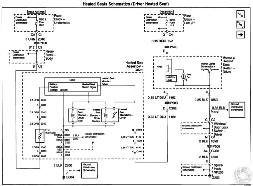
Posted By: dan33klein
Date Posted: November 11, 2017 at 10:02 AM
Thanks for the awesome write up.
I just want to double check before I install that the avital 4105l is the same wiring and installation as the 4103?
Thanks!
Posted By: kbenny
Date Posted: November 11, 2017 at 10:30 AM
I used this write up with no problems and I was installing a 4105L. I dont recall any differences in the wiring between the 2 models.
Posted By: dan33klein
Date Posted: November 11, 2017 at 12:26 PM
Thanks a lot.
I ordered all 3 items to install on my
Truck.
My factory remote fon barely works anyways. This will be a nice upgrade.
Posted By: dan33klein
Date Posted: November 11, 2017 at 12:27 PM
K benny,
Since you used the 4105l did you actually hook up the tach wire? Or did you use the virtual tach?
Posted By: kbenny
Date Posted: November 11, 2017 at 12:34 PM
I hooked up the tach wire, after researching it, because it was considered more reliable.
Posted By: rheckbert3
Date Posted: November 11, 2017 at 2:00 PM
dan33klein wrote:
K benny,
Since you used the 4105l did you actually hook up the tach wire? Or did you use the virtual tach?
I used the 4105l and hooked up the tach wire. Very easy. Wire can be easily found behind the Instrument Cluster.
dan33klein wrote:
Thanks for the awesome write up.
I just want to double check before I install that the avital 4105l is the same wiring and installation as the 4103?
Thanks!
The wiring should be basically the same between the 4103 and 4105. I used the 4105 and had no problems following Kreg's write up.
Posted By: dan33klein
Date Posted: November 15, 2017 at 7:14 PM
Thanks. I might as well hook up the tach wire also. I agree that it would be more reliable.
Posted By: dan33klein
Date Posted: November 16, 2017 at 12:09 PM
In this guide For the parking light connection it says + - and to set it positive. How do you set it to positive?
Sorry my kit is not here yet. I just want to be prepared.
Posted By: dan33klein
Date Posted: November 20, 2017 at 6:59 PM
Figured out the light output. Everything is installed and works great.
If installing a 4105l on a dispel vehicle, is there a way to wire in a wait to start input? Or do you have to use the timed function?
Posted By: kreg357
Date Posted: November 20, 2017 at 8:20 PM
There is no Wait To Start wire on a 4105. The only Diesel options are a fixed time delay.
-------------
Soldering is fun!
Posted By: kbenny
Date Posted: November 27, 2017 at 8:49 PM
If anyone on here has a 4105L and has also installed a DSM300 Smartstart module can you tell me if the wires from the 5 pin analog cable have to be connected?
I know the 12v+ and 12v- wires must be hooked up, along with the ESP 4 pin brown harness to the red ESP2/D2D port on the 4105L.
In the manual it says:
NOTE: The analog output wires are only active if the
device has been configured for Analog Wire mode in the
installation portal.
I am not familiar with what this is trying to explain.
Posted By: rheckbert3
Date Posted: November 27, 2017 at 9:56 PM
I believe you just need the power and ground connection as well as the D2D/ESP connection.
Posted By: kbenny
Date Posted: December 09, 2017 at 9:45 PM
Has anyone hooked up the blue/white -200mA wire to activate the rear window defroster and heated mirrors?
Just curious, I haven't dug into my dash yet to find out. I have the factory wiring diagram also but have to dig through 4 books the size of phone books to find it.
If anyone knows which wires to use and if a relay is needed please let me know.
Posted By: kbenny
Date Posted: December 09, 2017 at 9:46 PM
rheckbert3 wrote:
I believe you just need the power and ground connection as well as the D2D/ESP connection.
That is correct, just a 12v+ and 12v- and (on my 4105L) plug thee 3 wire harness adapter into the bitwriter port. Works great.
Posted By: kbenny
Date Posted: December 12, 2017 at 5:19 PM
If anyone on here can tell me how to do a "hard reset" on a dsm300 please let me know.
Everything on my system is working properly and the yellow and green lights are continuously lit solid.
I tried activating it and directed has informed me a dealer will need to do a "hard reset" to get it activated.
Tech support claims the unit was dormant for so long it will need this "hard reset" and I have no idea what they are talking about.
Any help is greatly appreciated.
Posted By: pedaltheglobe
Date Posted: January 07, 2018 at 4:46 PM
kbenny wrote:
Has anyone hooked up the blue/white -200mA wire to activate the rear window defroster and heated mirrors?
Just curious, I haven't dug into my dash yet to find out. I have the factory wiring diagram also but have to dig through 4 books the size of phone books to find it.
If anyone knows which wires to use and if a relay is needed please let me know.
I am also looking to do this on my 2002 Escalade EXT for my rear defogger, heated mirrors, and heated seats using a Viper 5704 and DB3 bypass module. I dont think any aftermarket bypass modules can control these on GM trucks on models older than 2003 due to them not being controlled by the databus. I do think I found a solution for the heated seats...
https://www.the12volt.com/installbay/forum_posts.asp?tid=93621&tpn=1
Also a solution for the rear defogger. Potentially the heated mirrors as well assuming this relay controls both...
https://www.the12volt.com/installbay/forum_posts.asp?tid=99413
If I use a relay that is signaled by the blue/white -200mA wire on the Viper 5704 to control the heated seats and then also use that wire to tap into the relay for the factory rear defogger relay do I need to diode isolate? How about if I go the other route mentioned in the linked thread and tap in at the climate control module so my rear defrost light is triggered as well. Do I need to diode isolate then?
Posted By: lurch228
Date Posted: March 18, 2018 at 1:46 AM
Diode isolate anytime you are connecting 2 circuits together to one activation wire to avoid back feed.
Posted By: slade725
Date Posted: December 09, 2019 at 7:34 PM
Where are you guys placing the remote start unit for these installs. I have mine under the knee kick panel, but don't like that location. Thanks
|