Relay Diagrams - Quick Reference
Printed From: the12volt.com
Forum Name: Relays
Forum Discription: Relay Diagrams, SPDT Relays, SPST Relays, DPDT Relays, Latching Relays, etc.
URL: https://www.the12volt.com/installbay/forum_posts.asp?tid=121342
Printed Date: May 12, 2026 at 1:22 AM
Topic: Relay Diagrams - Quick Reference
Posted By: the12volt
Subject: Relay Diagrams - Quick Reference
Date Posted: April 14, 2010 at 1:46 PM
Here's a new application I hope you'll find to be useful. Let me know what you think. https://www.the12volt.com/relays/relaydiagrams.asp -------------  the12volt Support the12volt.com the12volt Support the12volt.com
Replies:
Posted By: anonymous1
Date Posted: April 14, 2010 at 8:10 PM
This will be very beneficial. It's a lot easier to explain to someone how to make a single or double latching system if you already have diagrams as a reference, or the ability to take one and modify it and add as an attachment. Good stuff!
Posted By: i am an idiot
Date Posted: April 14, 2010 at 8:46 PM
I agree, it will be a lot easier than having to go to several pages to find what we need.
Posted By: the12volt
Date Posted: May 03, 2010 at 12:41 AM
Posted By: anonymous1
Date Posted: May 03, 2010 at 1:07 AM
That's a pretty comprehensive list you have. I have all seven volumes of the "Van Grafs Encyclopedia of Electronic Circuits" in .pdf format . . . with weigh so much less than the printed volumes i bought in the 90's. :D If I run across something else along these lines I will ping you, see what you think. I may have to slightly modify as to not incur copywright wrath, but I'm sure we can conjur something agreeable.
Posted By: the12volt
Date Posted: May 03, 2010 at 1:49 AM
Thanks. It's hard to believe I've been drawing them on paper in notebooks for more than 30 years and I'm just finding some time to create more graphics of some of them for the site. If you have something you want to share, feel free to shoot me an email (admin at the12volt.com) or post it here. We'd love to see it and share it with everyone else. ------------- the12volt Support the12volt.com
Posted By: anonymous1
Date Posted: May 03, 2010 at 2:07 AM
the12volt wrote:
Thanks. It's hard to believe I've been drawing them on paper in notebooks for more than 30 years
Some of my best work was done on napkins at Denny and IHOP for folks late at night. I would overhear the conversations of the engineering students as they re inented the wheel and drop them some nuggets. It's good to have more readily abailable PC tools to draw with now too, as apposed to the mid 90's and before. By chance, do you use FoxIT pdf software? Maybe we can talk more about the drawing topic in another thread as to not derail this one.
Posted By: the12volt
Date Posted: May 03, 2010 at 2:28 AM
Ha, yeah, I've drawn a few on napkins. I'm still using MS Paint to create these just like I did in the 90's :) No, I don't use FoxIT pdf software. ------------- the12volt Support the12volt.com
Posted By: oldspark
Date Posted: May 03, 2010 at 4:21 AM
MS Paint? You mean there are other packages available?
(At least you use color. I'm a Herculean - not into this modern CGA rubbish!)
And SIR the12volt, great stuff! You have already reached far & wide, yet you continue to improve, review etc.
All Hail the best voltage!
(It makes me wonder if Tesla was wrong after all...)
Posted By: the12volt
Date Posted: May 03, 2010 at 12:07 PM
lol... Thanks oldspark. With the exception of the logo and saving them as GIF's, it's all done in Paint. ------------- the12volt Support the12volt.com
Posted By: oldspark
Date Posted: May 03, 2010 at 8:22 PM
Ha - me too. So funny when I get the "you must have spent a lot of time on that diagram..." LOL! (Cut & pastes...)
But edit bmp's in Paint, then save as gif for posting/emailing ('cos I hate wasting massive bitspace) - often after cropping & conversion via IrfanView.
Posted By: anonymous1
Date Posted: May 03, 2010 at 8:36 PM
You guys should try the drawing function in the Foxit Pro pdf. Also, if you need to draw shapes in certain patterns or densities try this website = https://incompetech.com/graphpaper/ Or you can combine them. ------------- I know just enough to be dangerous. VERY dangerous.
Posted By: howie ll
Date Posted: June 26, 2010 at 5:17 PM
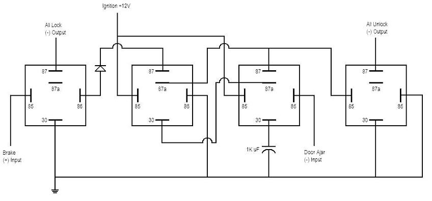
Great idea but I was just looking at one of the posts here about resetting auto lock after a door is opened, unfortunately the topic is closed BUT please look at his diagramme, the left hand relay can't work because how is it supposed to be triggered. the diagramme according to the diode layout shows NEG going to 85 AND 86.
Posted By: the12volt
Date Posted: June 26, 2010 at 6:55 PM
Howie, I'll be glad to look. Please post a link to the topic or post. ------------- the12volt Support the12volt.com
Posted By: howie ll
Date Posted: June 27, 2010 at 2:44 AM
Thanks, it's Add auto lock/unlock to Excursion/F250, I can't see how the left hand relay operates, there doesn't seem to be a POS coil feed.
Posted By: the12volt
Date Posted: June 27, 2010 at 11:53 AM
Looking at it closely, 85 is going to positive from the brake. All of his positive symbols seem to be missing the bottom part of the symbol.
https://www.the12volt.com/installbay/uploads/lock_and_unlock.jpg ------------- the12volt Support the12volt.com
Posted By: howie ll
Date Posted: June 27, 2010 at 12:01 PM
Take your point, just been watching the England F****ups and I was in a bad mood.
Posted By: hotwaterwizard
Date Posted: February 26, 2011 at 8:06 PM
I tried other programs for my drawings .
Paint is by far my choice.
I have all of my components saved in a BMP so I can just cut and paste them into a new BMP and make my drawings. ------------- John DeRosa (Hotwaterwizard)
Stockton California
When in doubt, try it out !
|