the12volt.com spacer
icon

relay to turn off power


Post ReplyPost New Topic
< Prev Topic Next Topic >
fourdoor 
Member - Posts: 3
Member spacespace
Joined: February 20, 2008
Location: California, United States
Posted: February 20, 2008 at 3:09 AM / IP Logged  
I apologize in advance if this is a basic question. I tried a quick search but couldn't find an exact answer/diagram that I thought matched my situation exactly. I just finished installing my rear view backup camera in my Nissan Titan. The location is on the rear bumper by the license plates. The camera has night vision capabilities.
The problem I have is that at night, the license plate illumination lights blind the rear view camera. I would like to be able to wire up a relay so that when I hit Reverse, the relay would cut off power to the license plate lights as to no longer blind the rear view camera.
From the basics of what I've read, I'm thinking of wiring up the BOSCH relay as so:
30 = Positive wire originally headed to license plate light (now source of + signal for license plate lights)
87a = Positive wire headed to actual license plate light
85 = Positive wire tapped into reverse signal wire
86 = Ground
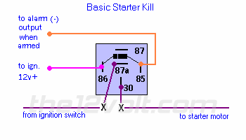
Similarly based on the starter kill diagram:
relay to turn off power -- posted image.
Is this the correct way of cutting off power via a relay? I have set up basic relays before to turn on accessories such as fog lights but have never used a relay before to turn off an accessory.
i am an idiot 
Platinum - Posts: 13,670
Platinum spaceThis member consistently provides reliable informationspace
Joined: September 21, 2006
Location: Louisiana, United States
Posted: February 20, 2008 at 5:40 AM / IP Logged  
That diagram is exaclty what you need.
fourdoor 
Member - Posts: 3
Member spacespace
Joined: February 20, 2008
Location: California, United States
Posted: February 20, 2008 at 11:22 AM / IP Logged  
Thanks. Are the connections I posted above correct then for my setup? Based on the diagram, it appears that I have the ground and signal reversed as the diagram has 85 as the negative ground.
Should my connections be like this instead then:
30 = Positive wire originally headed to license plate light (now source of + signal for license plate lights)
87a = Positive wire headed to actual license plate light
86 = Positive wire tapped into reverse signal wire
85 = Ground
i am an idiot 
Platinum - Posts: 13,670
Platinum spaceThis member consistently provides reliable informationspace
Joined: September 21, 2006
Location: Louisiana, United States
Posted: February 20, 2008 at 3:12 PM / IP Logged  
as long as you do not put the diode in the circuit it will not make a difference.  If the diode is used then it will matter.  If using the diode the band of the diode has to have the positive wire connected to it.
fourdoor 
Member - Posts: 3
Member spacespace
Joined: February 20, 2008
Location: California, United States
Posted: February 20, 2008 at 4:11 PM / IP Logged  
Not planning on installing any diodes. Thanks for the clarification. I'll give this a shot. :D
kaptan 
Member - Posts: 19
Member spacespace
Joined: July 22, 2005
Location: United States
Posted: April 25, 2008 at 9:16 PM / IP Logged  

Had to bump this back to the top, because I think this will do what I want it to..

FIRST THE STORY:   I've got a relay that turns on an electric fan, it has a thermostatic controler that activates the relay and of coarse then the fan runs from direct power from the battery.  Now, the controller has another wire that allows you to "bypass" the thermostat, and turn on the fan manually..BUT, when I wired this up using a simple on/off switch, it blew fuse after fuse, and now it has burned up the switch. I cannot find a short, It would work for a day or two, then the fuse would blow. Now the switch no longer works, but the thermostatic control does still work...

SO here's the solution I need help with.. I want to wire a relay to turn off the thermostatic controller, and run the fan, from a switch on the dash.. This is so I can run the fan manually to cool the A/C, when the radiator is not hot enough to turn on the fan. I've already been asked, why don't I just wire the fan to the A/C so that it runs when the A/C is on?... Answer: I take long trips and don't want the fan running as I'm traveling down the highway at 70 mph, with the A/C on for 3-4 hours... Please help.. I just can't see how to wire up the relay to cut something off, and turn something on at the same time...

Sony Mp3 HU, Dig/Aud 300Wts
(1) 12"sony sub.. Aint much, but it looks good, and thumps like a rabbit on Viagra!
i am an idiot 
Platinum - Posts: 13,670
Platinum spaceThis member consistently provides reliable informationspace
Joined: September 21, 2006
Location: Louisiana, United States
Posted: April 25, 2008 at 9:28 PM / IP Logged  

The relay on the controller, does it switch power or ground to the fan?   The fan will be supplied either power or ground, and get the other from the relay. Since you said it runs on power straight from the battery, I am assuming that the relay provides ground for the fan. This will be a piece of cake, I just need to know what you have to be able to draw you a picture.   This can be done with one additional relay and a switch, we won't even burn up a switch.

kaptan 
Member - Posts: 19
Member spacespace
Joined: July 22, 2005
Location: United States
Posted: April 26, 2008 at 7:36 AM / IP Logged  

Thank you so much for your help..

Actually, I'm pretty sure the controller relay supplies the (+) to the fan.. Seems like I remember running a ground wire from the fan and connecting it to the ground from the controller, and then connecting all the ground wires to the fenderwell, under one screw.  I've been running the problem through my head for 3 weeks now, and I'm starting to think that the problem might have been the spike from the relay.. it has no diode, and perhaps that could have been blowing my fuses? perhaps that could have toasted my switch?.. I dunno.. I barely have relays figgured out, I sure as hell don't know much about diodes.

Sony Mp3 HU, Dig/Aud 300Wts
(1) 12"sony sub.. Aint much, but it looks good, and thumps like a rabbit on Viagra!
i am an idiot 
Platinum - Posts: 13,670
Platinum spaceThis member consistently provides reliable informationspace
Joined: September 21, 2006
Location: Louisiana, United States
Posted: April 26, 2008 at 10:05 PM / IP Logged  
I am sure that the lack of a diode did not take out your switch. The only thing the diode does is prevent the spike that could cause a noise in your audio system. It will also not cause a fuse to blow. You had something connected wrong. When you check and can confirm that the fan is grounded and the controller provides it with 12 volts, I will be happy to draw you a diagram.
kaptan 
Member - Posts: 19
Member spacespace
Joined: July 22, 2005
Location: United States
Posted: April 26, 2008 at 10:20 PM / IP Logged  

Ok, I'm confused.. you say that the "lack of a diode took out the switch" but the fuse blowing was not caused by it? do I have that right? This is the problem. It all worked fine for about a month before the 1st fuse blew.. the second after about 5 days, and the 3rd and 4th fuses about the same.. THEN, the switch burned up, and it hasn't blown a fuse since. I dunno..It's like the switch was shorted, but I just couldn't find any evidence of that...anyway,  I did look, and the (-) wire from the fan, absolutley goes straight to ground. so It's a sure thing the controller/relay provides (+) to the fan.

Thanks again for your help, I always find folks on here willing to help..relay to turn off power -- posted image.

Sony Mp3 HU, Dig/Aud 300Wts
(1) 12"sony sub.. Aint much, but it looks good, and thumps like a rabbit on Viagra!
Page of 3

  Printable version Printable version Post ReplyPost New Topic
You cannot post new topics in this forum
You cannot reply to topics in this forum
You cannot delete your posts in this forum
You cannot edit your posts in this forum
You cannot create polls in this forum
You cannot vote in polls in this forum

  •  
Search the12volt.com
Follow the12volt.com Follow the12volt.com on Facebook
Tuesday, May 7, 2024 • Copyright © 1999-2024 the12volt.com, All Rights Reserved Privacy Policy & Use of Cookies
Disclaimer: *All information on this site ( the12volt.com ) is provided "as is" without any warranty of any kind, either expressed or implied, including but not limited to fitness for a particular use. Any user assumes the entire risk as to the accuracy and use of this information. Please verify all wire colors and diagrams before applying any information.

Secured by Sectigo
the12volt.com spacer
Support the12volt.com
Top
the12volt.com spacer