the12volt.com spacer
icon

Latching Relay to Flip Flop


Post ReplyPost New Topic
< Prev Topic Next Topic >
fairburnfarms 
Member - Posts: 2
Member spacespace
Joined: August 07, 2008
Location: Manitoba, Canada
Posted: August 07, 2008 at 3:12 PM / IP Logged  
Im hoping to make a standard 4PDT, Dual Coil latching relay into a "flip-flop" relay where i can trigger the relay once to close the circut and then trigger it again to open it up. I am having trouble thinking of a way to do this? anyone done it before?
i am an idiot 
Platinum - Posts: 13,663
Platinum spaceThis member consistently provides reliable informationspace
Joined: September 21, 2006
Location: Louisiana, United States
Posted: August 07, 2008 at 9:47 PM / IP Logged  

You could use the following to trigger your 4PDT relay

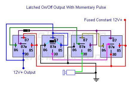
Latched On/Off Output Using a Single Momentary Pulse

Similar to the momentary to constant configuration above, we can engage and disengage the latched output with a single pulse from a switch or an output from an alarm or remote keyless entry. The first pulse from the switch will engage the latch. The next pulse from the switch will disengage the latch.
 
Latching Relay to Flip Flop -- posted image.
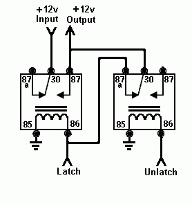
Here's the same configuration as the one above that you can use if you do not have any *diodes available and/or only want to use SPDT relays. A negative output from an alarm, remote keyless entry, or other device can be used in place of the switch shown in both of these diagrams.
 
Latching Relay to Flip Flop -- posted image.
 
hotwaterwizard 
Silver - Posts: 1,350
Silver spacespace
Joined: December 11, 2003
Location: California, United States
Posted: August 08, 2008 at 9:49 PM / IP Logged  
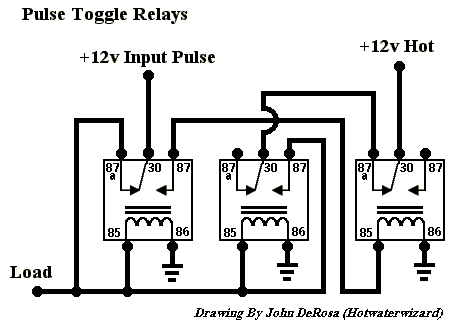
Latching Relay to Flip Flop -- posted image.
John DeRosa (Hotwaterwizard)
Stockton California
When in doubt, try it out !
hotwaterwizard 
Silver - Posts: 1,350
Silver spacespace
Joined: December 11, 2003
Location: California, United States
Posted: August 08, 2008 at 9:53 PM / IP Logged  
Latching Relay to Flip Flop -- posted image.
John DeRosa (Hotwaterwizard)
Stockton California
When in doubt, try it out !
hotwaterwizard 
Silver - Posts: 1,350
Silver spacespace
Joined: December 11, 2003
Location: California, United States
Posted: August 08, 2008 at 9:56 PM / IP Logged  
Latching Relay to Flip Flop -- posted image.
John DeRosa (Hotwaterwizard)
Stockton California
When in doubt, try it out !
94 gt vert 
Member - Posts: 6
Member spacespace
Joined: August 10, 2008
Location: Texas, United States
Posted: August 10, 2008 at 2:59 PM / IP Logged  

I had the same problem with an access control system I was working on. Turned out to be a very simple solution. I found a relay that changes states everytime it gets power to it. I used a N/O pushbutton to activate it.

I dont know the part number of the relay but I can tell you I got it at L&M electronics.  Sorry if I am not much help.

94 GT Convertable
hotwaterwizard 
Silver - Posts: 1,350
Silver spacespace
Joined: December 11, 2003
Location: California, United States
Posted: August 10, 2008 at 9:28 PM / IP Logged  

Latching Relay to Flip Flop -- posted image.

http://www.mcmelectronics.com/product/28-5115

CEBEK - Flip-Flop Relay Module MCM Part #: 28-5115

Product Details:

With momentary contact at the input, the output relay closes and latches.
Upon a second momentary closure of the same input, the relay opens.
Relay contacts 5A Requires 12VDC, 50mA.
Board dimensions 60mm x 60mm x 30mm.

http://www.mcmelectronics.com/content/productimages/s4/3930919.jpg

http://www.quasarelectronics.com/ci0009.htm

CI0009 - CEBEK - Flip-Flop Relay ModuleElectronic Flip-Flop Relay Board Module

Simple push button operation using either one or two switches to toggle the onboard
mains rated relay on and off.
Use with a single push switch to both start and stop or two push buttons;
One to start and one to stop.

The module has protection against inverse polarity,

indicator output LED and screw terminal connectors.
Requires external 12V dc power supply  (Order Code CFE103).

http://www.quasarelectronics.com/images/cebek/ci0009.jpg

Newark Part Number: 36C6492

Manufacturer Part No: 28-5115

Description

Cebek Electronic Circuits Flip-Flop Relay Module,
Relay Contacts: 5 A, Power Requirements: 12 VDC, 50 mA,
 Board Dimensions: 60 x 60 x 30 mm,
Features: With momentary contact at the input,
 the output relay closes and latches

http://www.newark.com/jsp/search/productdetail.jsp?SKU=36C6492&CMP=AFC-TL10000001

http://fadisel.com/cebek-electronic/automatisms/flip-flop-automatism-cebek-i-9_R_390.aspx

power supply  12 / 60 mA 

maximum load  5A 
dimensions  61 x 40 x 30 mm. 
weight  50 grs. 
 
Information I-9 
Automatism with relay allowing any load.
Injecting impulses, for each one, the module will alternately connect or disconnect
the output in a start and stop sequence.
It could operate with a single signal input making one operation per impulse.
On-Off with two inputs one for each operation. Maxi. Load : 5 A.
Power Supply: 12 V. D.C. / 60 mA. (Module FE-103 

https://img.icnea.net/Forum/E6001/fotos/I-9-NOU.jpg

User Manual

https://img.icnea.net/Forum/E6001/ftp/I-009_Ang.pdf

John DeRosa (Hotwaterwizard)
Stockton California
When in doubt, try it out !
fairburnfarms 
Member - Posts: 2
Member spacespace
Joined: August 07, 2008
Location: Manitoba, Canada
Posted: August 12, 2008 at 10:07 PM / IP Logged  
thanks for the help. That would work fine
hotwaterwizard 
Silver - Posts: 1,350
Silver spacespace
Joined: December 11, 2003
Location: California, United States
Posted: August 12, 2008 at 10:40 PM / IP Logged  

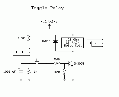
If you would like to make one yourself here is the Schematic. It is from http://ourworld.compuserve.com/homepages/Bill_Bowden/page9.htm

Latching Relay to Flip Flop -- posted image.

John DeRosa (Hotwaterwizard)
Stockton California
When in doubt, try it out !

Sorry, you can NOT post a reply.
This topic is closed.

  Printable version Printable version Post ReplyPost New Topic
You cannot post new topics in this forum
You cannot reply to topics in this forum
You cannot delete your posts in this forum
You cannot edit your posts in this forum
You cannot create polls in this forum
You cannot vote in polls in this forum

  •  
Search the12volt.com
Follow the12volt.com Follow the12volt.com on Facebook
Tuesday, March 19, 2024 • Copyright © 1999-2024 the12volt.com, All Rights Reserved Privacy Policy & Use of Cookies
Disclaimer: *All information on this site ( the12volt.com ) is provided "as is" without any warranty of any kind, either expressed or implied, including but not limited to fitness for a particular use. Any user assumes the entire risk as to the accuracy and use of this information. Please verify all wire colors and diagrams before applying any information.

Secured by Sectigo
the12volt.com spacer
Support the12volt.com
Top
the12volt.com spacer