the12volt.com spacer
icon

power window motor with relay


Post ReplyPost New Topic
< Prev Topic Next Topic >
rdietze23 
Member - Posts: 6
Member spacespace
Joined: March 14, 2014
Posted: March 14, 2014 at 11:40 PM / IP Logged  
Hello everybody,
I am building a railroad crossing with the arm that goes up and down for my son and I need a little help on how to make a circuit. I have a power window motor, 12v relays, 12v battery, and a power window switch that has 5 pins. My goal is if you push the down arrow for one second and release, the power window motor turns on and stays on until the arm goes all the way down and I will have a push button switch that the arm will hit to kill the power so the arm stops at the correct position. When the up button is pushed the arm goes up by itself and when it gets to the top the arm will hit another push button switch to stop the window motor. I have seen circuits where they use a latching relay to make this work, but just unsure how to actually wire this so this can happen. Does anybody have any thoughts or ideas on how I can accomplish this? My son will really like this project if I can make it work. Thanks in advance
oldspark 
Gold - Posts: 4,913
Gold spacespace
Joined: November 03, 2008
Location: Australia
Posted: March 15, 2014 at 2:12 AM / IP Logged  
You'd either use limit switches or sensors (optic etc) to sense when the boom is at each limit of travel, or you'd use a timer adjusted for the anticipated travel time.
I prefer limit switches - maybe micro-switches, else photo-interrupting type optics, though a magnet and reed switches might be the simplest.
What's your preference?
rdietze23 
Member - Posts: 6
Member spacespace
Joined: March 14, 2014
Posted: March 15, 2014 at 9:40 AM / IP Logged  
Thanks for the reply. I actually have some micro switches I am going to use. Any idea on how to wire this circuit? I have some automobile relays and a up and down car window switch. Which wires go into the relays? I want to use a latching relay circuit so the motor stays on until the switch turns it off at the correct location of the arm. Or is a latching circuit not going to work? Thanks again.
oldspark 
Gold - Posts: 4,913
Gold spacespace
Joined: November 03, 2008
Location: Australia
Posted: March 15, 2014 at 10:56 AM / IP Logged  
I'm not capable of quality thinking at the moment, but I was thinking of a common method use to latch plain relays as shown in type of relay or suggestions but where the normally closed limit switch is inserted between output 87 and coil 86. When the limit is reached, the switch opens and hence breaking the +12V supply from 87 to 86 so the relay de-energises, but that means using DT limit (micro) switches - ie, SPDT.
That method is shown in the diagram below noting that the diodes are only there to prevent the on or "start" switch supplying the load (motor) until the relay closes (30 connects to 87).
But more is required relay-wise since each relay must switch + & - (or +12V & 0V aka GND) to the motor as required for each direction of travel. And preferably some lockout so that BOTH directions (switches) cannot act simultaneously and hence short +12V to GND.
I'm confident it can be done simply, but that might come after some sleep....
power window motor with relay -- posted image.
rdietze23 
Member - Posts: 6
Member spacespace
Joined: March 14, 2014
Posted: March 16, 2014 at 1:52 PM / IP Logged  
Thanks for the guidance and visual. I was able hook up this latching relay with a couple push buttons. worked well. If I can only go one direction, I can work with that, but it sounds like it might get confusing or might be difficult to add another switch to or use a car window switch to be able to switch the polarity and make the motor go the other direction. Is it pretty difficult to make this work? If so I might just stick to one direction.
Thanks again.
rdietze23 
Member - Posts: 6
Member spacespace
Joined: March 14, 2014
Posted: March 16, 2014 at 10:56 PM / IP Logged  
I did a little more research on how they power a window unit, where you physically have to push down the button and hold it to power the window motor. If it is released then the motor shuts off. If the button is pushed the other way then, the motor goes the other way. I see that this circuit ussd two relays. What if there is a way you can use a toggle switch, when turned on one direction the motor turns one direction and there is some sort of limit switch or push button that turns the power off. Then if the toggle switch is pushed the other way then the motor turns the other direction, then when the arm reaches the desired location, there will be another limit switch or push button that turns the power off. Do you think this is possible?
oldspark 
Gold - Posts: 4,913
Gold spacespace
Joined: November 03, 2008
Location: Australia
Posted: March 17, 2014 at 12:25 AM / IP Logged  
I'm still not fully thinking, but to cover some basics...
The top right diagram on Rollertrol's DC motor reverse switch shows the typical wiring for motor reversing using a centre-off DPDT switch.
The equivalent SPST relay version of the above switch wiring is as per 4crawler.com's 4Runner Rear Window Cheap Tricks, namely:
power window motor with relay -- posted image.
OR, as per blog.solidremote.com's Using Remote Control Relay to Control DC Motor Forward and Reverse, namely:
power window motor with relay -- posted image.
If interested, I'd suggest looking at REUK's Automatic Hen House Door Closer Opener page for a bit more info relating to the above two SPST relays implementation. Note that the shorting of +12V to GND is prevented - ie, the 2nd Hen House diagram when BOTH relays are actuated.
The relays could be controlled by a low current centre-off SPDT switch or whatever control circuitry you use.
The above relay wiring is also depicted in the12volt's Relay Diagrams - Door Locks - Actuators / Reverse Polarity - Positive Switch/Trigger, namely:
power window motor with relay -- posted image.
... where the Lock Actuator is replaced by the motor.
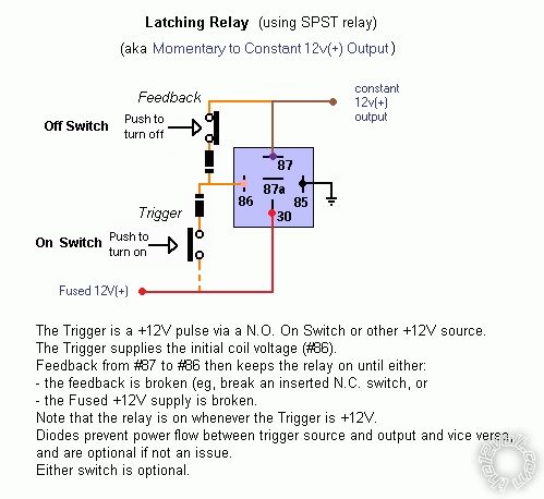
Note that the above shows +12V to trigger the relays, but 0V (GND) can be used with some rewiring as shown in the Relays (door locks) section.
And FWIW, instructables How to wire a 12v motor and limit switches to... has the following diagram noting that its car ignition control (via the Changeover switch in timer) may not suit your application.
power window motor with relay -- posted image.
rdietze23 
Member - Posts: 6
Member spacespace
Joined: March 14, 2014
Posted: March 21, 2014 at 9:55 PM / IP Logged  
Thanks for all of the good info. I tried to wire it up from your 2nd to the bottom diagram and had no luck. I was using a DTDP switch. I then just hooked up the circuit without the relays and got the motor to to turn both directions. What if I just went without the relays and just used the switch, motor and limit switches? What do the relays do that would benefit the circuit I am trying to do? Also, when I use the two limit switches, when the boom reaches its destination and the limit switch is activated turning off the circuit, when I turn the motor to go the other direction wouldn't the circuit not work because the limit switch is still in the off position? How could it be wired where if I use a toggle switch that has no off position (either going in one direction or the other) and use 2 limit switches where I turn the toggle switch one direction activating the boom, limit switch turns off motor, then the toggle switch is turned in the other direction turning the motor the other direction. Thanks again for all of your help.
rdietze23 
Member - Posts: 6
Member spacespace
Joined: March 14, 2014
Posted: March 22, 2014 at 5:04 PM / IP Logged  
sorry for all of the replies, but I went back and tried to connect the circuit again with the two relays using the 2nd from the bottom diagram. Hooking it up exactly shown, I can get both 85 & 86's to click when pushing the button both directions, but I still don't have any power going to the motor.I feel like its something in the 87 and 30 connection, but again I have it wired up just like the diagram shows. Any thoughts?

Sorry, you can NOT post a reply.
This topic is closed.

  Printable version Printable version Post ReplyPost New Topic
You cannot post new topics in this forum
You cannot reply to topics in this forum
You cannot delete your posts in this forum
You cannot edit your posts in this forum
You cannot create polls in this forum
You cannot vote in polls in this forum

  •  
Search the12volt.com
Follow the12volt.com Follow the12volt.com on Facebook
Thursday, March 28, 2024 • Copyright © 1999-2024 the12volt.com, All Rights Reserved Privacy Policy & Use of Cookies
Disclaimer: *All information on this site ( the12volt.com ) is provided "as is" without any warranty of any kind, either expressed or implied, including but not limited to fitness for a particular use. Any user assumes the entire risk as to the accuracy and use of this information. Please verify all wire colors and diagrams before applying any information.

Secured by Sectigo
the12volt.com spacer
Support the12volt.com
Top
the12volt.com spacer