the12volt.com spacer
icon

Crimestopper CS-2003DC in '01 dodge ram


Post ReplyPost New Topic
< Prev Topic Next Topic >
goldshop 
Member - Posts: 4
Member spacespace
Joined: November 30, 2003
Posted: November 30, 2003 at 9:58 PM / IP Logged  

I'm installing a Crimestopper CS-2003DC in a 2001 Dodge Ram 3500. I uploaded a copy of the alarm wiring diagram at: http://www.houstonhost.com/cs-2003dc.htm . The diagrams shows negative and positive trigger doorlock wiring but nothing on 5-wire doorlocks. From what I've read my ram has 5-wire locks. Can anyone help with an answer on how to connect the alarm wiring to Ram doorlocks. Since this is my first alarm I would also appreciate any other suggestions. Thank you.

Goldshop

goldshop@ev1.net


gtchida 
Copper - Posts: 89
Copper spacespace
Joined: August 20, 2003
Location: United States
Posted: December 01, 2003 at 12:17 AM / IP Logged  

Try this https://www.the12volt.com/doorlocks/page3.asp#5w - it's fairly straightforward. I have an o1 Ram that I just did if you have any other questions. You can grab the wires at the drivers kick panel. Do a search in the car security forum for the wiring diagram. Let me know if you need any other help.

Gary

gtchida@cox.net

goldshop 
Member - Posts: 4
Member spacespace
Joined: November 30, 2003
Posted: December 01, 2003 at 12:59 AM / IP Logged  

My alarm has built in onboard relays. You can see the alarm power door lock diagrams  on the bottom of http://www.houstonhost.com/cs-2003dc.htm . Will this make a differents on the hook up or will I need to add two relay as it the diagram link above?

Goldshop

mobiletoys2002 
Gold - Posts: 1,050
Gold spacespace
Joined: April 12, 2002
Location: United States
Posted: December 01, 2003 at 9:08 AM / IP Logged  
you wont need relays all you have to do is find the right door lock wires in the vehicle.
cut one of the suspect wires and you should lose operation of one of the switches. Now take a meter and ground the black lead, Now take the red and place on one side of the cut wire try to unlock if no voltage comes up place the red on the opposite side of the cut wire now 12 volts should show when the door lock switch is pressed, this is the switch side now wire the switch side to 87a and the other side goes to 30. Now do the same for the remaining wire and wire exctly the same- find the switch side and wire it as stated above.
pin 87 will get 12 volts positive. good luck
goldshop 
Member - Posts: 4
Member spacespace
Joined: November 30, 2003
Posted: December 01, 2003 at 12:07 PM / IP Logged  

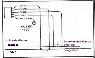
I'm still not sure if I understand the lock/unlock wiring. From what I read in the forum my truck has unlock wiring "ORANGE / violet"and lock wiring "pink/violet". Both lock and unlock wiring in the driver door harness.

Is this right? The alarm lock/unlock wiring harness violet wire goes to + 12V.  White wire goes to power side of cut ORANGE / violet wire. Green wire goes to other side of ORANGE / violet wire with no power.

Blue wire goes to power side of cut pink/violet wire. Brown wire goes to other side of pink/violet wire with no power.

  http://www.houstonhost.com/cs-2003dc.htm  to see complete alarm diagram. If you use dial up like myself please be patient it will take a little while to fully load.

Goldshop

Crimestopper CS-2003DC in '01 dodge ram - Last Post -- posted image.

goldshop 
Member - Posts: 4
Member spacespace
Joined: November 30, 2003
Posted: December 02, 2003 at 6:51 PM / IP Logged  

I started installing my alarm after work today. Ran out of daylight, I hope I will be able to finish tomorrow evening. I could not find the central timer module. I read in this forum it is on the right side of the steering column. Under the dash on the passenger side of the steering  column was the brake switch but no other wiring close by. Can someone tell me what the central timer module looks like and how many wires (or about how many)is connected to it. Thanks guys for all the help.

Goldshop


Sorry, you can NOT post a reply.
This topic is closed.

  Printable version Printable version Post ReplyPost New Topic
You cannot post new topics in this forum
You cannot reply to topics in this forum
You cannot delete your posts in this forum
You cannot edit your posts in this forum
You cannot create polls in this forum
You cannot vote in polls in this forum

  •  
Search the12volt.com
Follow the12volt.com Follow the12volt.com on Facebook
Thursday, October 31, 2024 • Copyright © 1999-2024 the12volt.com, All Rights Reserved Privacy Policy & Use of Cookies
Disclaimer: *All information on this site ( the12volt.com ) is provided "as is" without any warranty of any kind, either expressed or implied, including but not limited to fitness for a particular use. Any user assumes the entire risk as to the accuracy and use of this information. Please verify all wire colors and diagrams before applying any information.

Secured by Sectigo
the12volt.com spacer
Support the12volt.com
Top
the12volt.com spacer