the12volt.com spacer
icon

2006 f 150 xlt door lock wiring


Post ReplyPost New Topic
< Prev Topic Next Topic >
dennis franz 
Member - Posts: 2
Member spacespace
Joined: February 07, 2007
Location: United States
Posted: February 13, 2007 at 5:27 PM / IP Logged  

I plan on installing a Code-Alarm CA-670 into an 06 F-150 XLT with factory RKE.

I want to keep the 2-step unlock unlock feature. My question is how do I connect the RKE module along with the CA-670  to keep the 2-step unlock?

http://www.code-alarm.com/manuals/installation/CA610Inst_%20revD_122105.pdf

In the CA-670 installation manual found above,  pg 20 shows serveral diagrams for wiring and directechs has notes that this is a 5-wire system. Directechs state the POWER L/UL is a neg system.

Do I have to cut wirie or tap in? Do I have to make a 2-relay wiring for a typical 5 wire system and will that trigger the 2-step RKE module?

Can I get some direction on which setup I need for the alarm and vehicle or am I making this more complicated than it is.

Truck Color Coding:

Power Lock
Power Unlock
Lock Motor
Unlock Motor
Disarm Defeat

Alarm Color Wiring

1

NEG LOCK/POS UNLOCK

GREEN

2

NEG UNLOCK/POS LOCK

BLUE

3

2ND STAGE UNLOCK

BLUE/GREEN

Thanks for any and all help guys!

NowYaKnow 
Gold - Posts: 1,217
Gold spacespace
Joined: December 18, 2002
Posted: February 13, 2007 at 5:34 PM / IP Logged  
You should run the green wire to the pink / YELLOW wire in the drivers door sill harness.
You should run the blue/green to the pink/green wire in the drivers door sill harness.
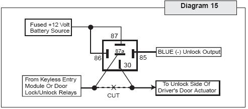
You should run the blue wire to pin 85 on a relay. Pins 86 and 87 should go to 12volts constant, fused. Find the RED / orange driver door unlock motor wire in the drivers kick and cut it. The switch side connects to pin 87a on the relay, and the motor side to pin 30.
Mike
dennis franz 
Member - Posts: 2
Member spacespace
Joined: February 07, 2007
Location: United States
Posted: February 13, 2007 at 5:46 PM / IP Logged  

Mike,

Ican't thank you enough. Wow, 7 minutes for a reply. Better than tech-support line.

So I will use the diagram listed below perfectly as you noted.
I REALLY appreciate your prompt reply and help.
Damned glad I joined this group.
2006 f 150 xlt door lock wiring - Last Post -- posted image.


Sorry, you can NOT post a reply.
This topic is closed.

  Printable version Printable version Post ReplyPost New Topic
You cannot post new topics in this forum
You cannot reply to topics in this forum
You cannot delete your posts in this forum
You cannot edit your posts in this forum
You cannot create polls in this forum
You cannot vote in polls in this forum

  •  
Search the12volt.com
Follow the12volt.com Follow the12volt.com on Facebook
Thursday, October 31, 2024 • Copyright © 1999-2024 the12volt.com, All Rights Reserved Privacy Policy & Use of Cookies
Disclaimer: *All information on this site ( the12volt.com ) is provided "as is" without any warranty of any kind, either expressed or implied, including but not limited to fitness for a particular use. Any user assumes the entire risk as to the accuracy and use of this information. Please verify all wire colors and diagrams before applying any information.

Secured by Sectigo
the12volt.com spacer
Support the12volt.com
Top
the12volt.com spacer