the12volt.com spacer
icon

fixing remote start, 1999 ford f150


Post ReplyPost New Topic
< Prev Topic Next Topic >
brian_mcenulty 
Member - Posts: 39
Member spacespace
Joined: March 30, 2004
Location: United States
Posted: September 20, 2007 at 5:58 PM / IP Logged  
Hey guys I have a 1999 Ford F150 and an Audiovox Prestige APS996a remote starter intalled. I originally had the DEI555f PATS bypass installed but it's a piece of crap and doesn't work half the time so I bought a DEI555p to replace it since it doesn't rely on being placed right next to the ignition switch. I also have aftermarket DEI door lock actuators installed in my truck because the OEM ones stopped working. My first question is does anyone know the proper wires to hook the 555p up to? (I can get the alarm signal wire, 12v and ground just fine, but the others I'm unsure about). My second question is I have the DEI lock actuators wired up using 2 relays with the 5 wire setup that is posted on this site, the actuators work great using the switches but don't work at all with the keyless entry. I have the lock/unlock wires hooked up to the relays that I wired up according to the diagram on this site. Any help at all would be appreciated, thanks!
chadwa2003 
Copper - Posts: 353
Copper spacespace
Joined: January 08, 2005
Location: Canada
Posted: September 20, 2007 at 7:50 PM / IP Logged  
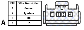
Post up the diagram or a link to the diagram and we can help you out better but of the top of my head 85 is the lock or unlock output from the alarm, 86 and 87 are connected to 12v constant, 87a goes to ground and 30 goes to the actuators. In terms of the pats wiring you should see a 4 pin connector at the key cylinder one wire is ground other is ignition and then your 2 left over wires are tx and rx. They usually very from cars but it could be WHITE/ green and grey/orange, but you should have gotten some info with it
aggieman2002 
Member - Posts: 6
Member spacespace
Joined: September 17, 2007
Location: Maryland, United States
Posted: September 20, 2007 at 8:00 PM / IP Logged  

It sounds like you you have the switch side and the motor side backwards on the relay.  Where you cut the wire, the switch side should read 12 volts when you press the switch to lock or unlock, motor side reads 0. So I would test the that connection at the relay, if that not it, I don't know what could be. Sorry I don't know how the 555p, I always use 556UW, which requires an extra key.

init 
Copper - Posts: 93
Copper spacespace
Joined: March 13, 2007
Location: Louisiana, United States
Posted: September 20, 2007 at 8:42 PM / IP Logged  

fixing remote start, 1999 ford f150  - Last Post -- posted image.

I'll agree the manual that comes with the 555P isn't much help, but the diagrams that come in DEI's latest one is.  From what I can tell your harness is the same as the one in my Explorer, which is also a 99, and the diagram above shows what it looks like.  According to this, Rx is pin 3 and Tx is pin 4.  As far as the Rx and Tx wires go there really isn't any way of testing them, but when I wired mine up the wires were in the position as shown in this diagram.  If you look closely at the harness, which is behind the panel underneath the steering column, it has the pin numbers on the harness, too.  Remember to either solder or crimp the connections for the bypass.

I'm not a professional installer. But I did stay at a Holiday Inn Express.
brian_mcenulty 
Member - Posts: 39
Member spacespace
Joined: March 30, 2004
Location: United States
Posted: September 21, 2007 at 2:39 AM / IP Logged  
Thanks for the fast replies and great info guys, I'll go ahead and give it a go tomorrow afternoon and see if it all works. Thanks again
brian_mcenulty 
Member - Posts: 39
Member spacespace
Joined: March 30, 2004
Location: United States
Posted: September 21, 2007 at 6:57 PM / IP Logged  
Ok I'm trying to figure out these locks right now. I have the relays right underneath the door lock switches so that's the location of that, and the way it's wired up is like this:
30 - Actuator
86 - 12v constant
87 - 12v constant
87a - Switch wire
85 - Alarm lock/unlock output
I have 1 relay for lock and one for unlock. The switch works great but the alarm does nothing when using the keyless entry
brian_mcenulty 
Member - Posts: 39
Member spacespace
Joined: March 30, 2004
Location: United States
Posted: September 21, 2007 at 7:30 PM / IP Logged  
Another thing, I was able to find the Tx and Rx wires just fine, right where you said they were. I am having trouble though understanding what to do with the Pink and the Pink/White wires one the 555p. In the instructions it says to cut the ignition wire and connect the pink wire to the car side and the pink/white to the key side. Can anyone elaborate on this for me? Thanks!
wrenches 
Member - Posts: 44
Member spacespace
Joined: October 22, 2006
Location: Ontario, Canada
Posted: September 21, 2007 at 7:57 PM / IP Logged  
Pin 2 of the 4 pin plug ou hooked up the rx and tx on is the ignition feed for the PATS system.  DEI needs it to be interupted when the 555p getspowered up by the remote start.  Cut that wire, the side of the wire that goes to the key cylinder gets hooked to the pink/white, the other side gets hooked up to the pink.
brian_mcenulty 
Member - Posts: 39
Member spacespace
Joined: March 30, 2004
Location: United States
Posted: September 21, 2007 at 9:28 PM / IP Logged  
Well I got the remote starter working good now, thanks for the help! Now I just need to figure out my locks and I'll be set
chadwa2003 
Copper - Posts: 353
Copper spacespace
Joined: January 08, 2005
Location: Canada
Posted: September 22, 2007 at 7:26 PM / IP Logged  
brian_mcenulty wrote:
Ok I'm trying to figure out these locks right now. I have the relays right underneath the door lock switches so that's the location of that, and the way it's wired up is like this:
30 - Actuator
86 - 12v constant
87 - 12v constant
87a - Switch wire
85 - Alarm lock/unlock output
I have 1 relay for lock and one for unlock. The switch works great but the alarm does nothing when using the keyless entry
If you are adding aftermarket actuators which from the sounds of your orignal post you are. Your wiring is almost correct you should have a blue and green wire coming off your actuators, you will need to connect one to 30 of one relay and the other one to 30 of the other relay. Connect 87a to ground and that should do it. Are you installing an aftermarket switch as well?

Sorry, you can NOT post a reply.
This topic is closed.

  Printable version Printable version Post ReplyPost New Topic
You cannot post new topics in this forum
You cannot reply to topics in this forum
You cannot delete your posts in this forum
You cannot edit your posts in this forum
You cannot create polls in this forum
You cannot vote in polls in this forum

  •  
Search the12volt.com
Follow the12volt.com Follow the12volt.com on Facebook
Thursday, October 31, 2024 • Copyright © 1999-2024 the12volt.com, All Rights Reserved Privacy Policy & Use of Cookies
Disclaimer: *All information on this site ( the12volt.com ) is provided "as is" without any warranty of any kind, either expressed or implied, including but not limited to fitness for a particular use. Any user assumes the entire risk as to the accuracy and use of this information. Please verify all wire colors and diagrams before applying any information.

Secured by Sectigo
the12volt.com spacer
Support the12volt.com
Top
the12volt.com spacer