Posted: April 13, 2008 at 3:22 PM / IP Logged
Posted: April 13, 2008 at 3:40 PM / IP Logged
Posted: April 14, 2008 at 1:35 AM / IP Logged
Posted: April 14, 2008 at 3:27 AM / IP Logged
Posted: April 14, 2008 at 4:16 AM / IP Logged
Posted: April 14, 2008 at 5:52 AM / IP Logged
Posted: April 14, 2008 at 6:00 AM / IP Logged
Posted: April 14, 2008 at 7:15 AM / IP Logged
Posted: April 14, 2008 at 7:39 AM / IP Logged
Posted: April 14, 2008 at 7:50 AM / IP Logged
 Printable version


| You cannot post new topics in this forum You cannot reply to topics in this forum You cannot delete your posts in this forum You cannot edit your posts in this forum You cannot create polls in this forum You cannot vote in polls in this forum |

| Search the12volt.com |
Follow the12volt.com 
Wednesday, May 8, 2024 • Copyright © 1999-2024 the12volt.com, All Rights Reserved • Privacy Policy & Use of Cookies


Wednesday, May 8, 2024 • Copyright © 1999-2024 the12volt.com, All Rights Reserved • Privacy Policy & Use of Cookies
Disclaimer:
*All information on this site ( the12volt.com ) is provided "as is" without any warranty of any kind, either expressed or implied, including but not limited to fitness for a particular use. Any user assumes the entire risk as to the accuracy and use of this information. Please
verify all wire colors and diagrams before applying any information.


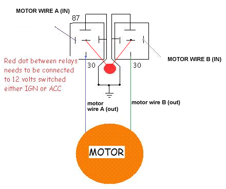
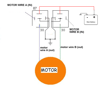
 Here is my current switch setup, basically the driver side is connected to the passenger side, with 3 wires. One is always +ve, while the 2 others are "control" wires, that are +ve or -ve according to the switch pressed in the driver's side. Irrespective of which switch is pressed (driver side or passenger), the output to motor (labeled wire A & B), are either both "nothing" (0v I presume), or A +ve, B -ve in for going up, and A -ve, B +ve when going down.
 I've changed the ground and +ve feed as you said. I was not sure with the "switched +ve 12V" on top, but I did a dry run on the circuit and it seems as it should be ground, for it to work well. I don't know if this is correct, but I think the relay setup should go in between the switch and the motor, thus it would involve cutting the wire A and wire B, and connecting the wire A and wire B from the switches to the "switches input" of the relay diagram, and the outputs that should go to the motor to the other end of wire A and wire B. Correct me if i'm wrong, please.

