the12volt.com spacer
icon

two second ground out without pulse timer


Post ReplyPost New Topic
< Prev Topic Next Topic >
Kcautosound 
Member - Posts: 33
Member spacespace
Joined: December 27, 2004
Location: United States
Posted: October 02, 2009 at 10:51 PM / IP Logged  
Guys. Without the use of a expensive pulse timer how would I go about getting the relay to hold a ground for about two second or so without a flash. I know how to make the relay change positive to negative but then I need it to hold the negative output for about two seconds. I have to use two of these so it gets pretty expensive using two pulse timers.
howie ll 
Pot Metal - Posts: 16,466
Pot Metal spacespace
Joined: January 09, 2007
Location: United Kingdom
Posted: October 03, 2009 at 3:02 AM / IP Logged  
Diagrammes are on this site in the relay section.
i am an idiot 
Platinum - Posts: 13,671
Platinum spaceThis member consistently provides reliable informationspace
Joined: September 21, 2006
Location: Louisiana, United States
Posted: October 03, 2009 at 3:53 AM / IP Logged  

What signal do you have to initiate the cycle?   Do you have a ground out when armed that you need to make into a 2 second pulse?  Or do you have a short ground out pulse that you need to extend to make it a 2 second duration?

dualsport 
Silver - Posts: 983
Silver spacespace
Joined: September 27, 2005
Location: United States
Posted: October 03, 2009 at 6:05 AM / IP Logged  
delay circuit
If it's a positive pulse trigger you're using as an input, and you just need a ground output maintained for a short duration after the pulse, you can try this. Just change the values of the resistor and cap to smaller values to get the short 2 sec delay.
If you only need the output as a signal rather and not driving something, you can delete the relay, since the transistor puts the ground out directly.
Can't get much less expensive than that, since the parts should run less than a postage stamp.
Kcautosound 
Member - Posts: 33
Member spacespace
Joined: December 27, 2004
Location: United States
Posted: October 03, 2009 at 8:33 AM / IP Logged  
Thanks for the help guys.
What I'm doing with this is using the door lock motor positive wires to drive relays to produce negative arm and disarm inputs on an alarm. I'm running into some vehicles that they flash too quick of a positive pulse for the alarm to see it. An example problem vehicle I run into is the 2004-08 F150s. The pulse seems to go so fast that it doesn't always allow the relay to fire off a long enough ground out pulse for the alarm to see it, yet if I use a Code Alarm PTM1 pulse timer set to the lowest setting (about 1 1/2 seconds) it works perfect. Just gets expensive when I need two of these timers and they cost me $14.00 each. I use a ton of them. Just trying to maybe create a circuit that I can build and save me some money and time of ordering all these timers in all the time. My distribution can't keep up with my demand for the timers and I've got waiting customers all the time because I'm waiting for the timers to come back in. The PAC TR7 is even more money.
i am an idiot 
Platinum - Posts: 13,671
Platinum spaceThis member consistently provides reliable informationspace
Joined: September 21, 2006
Location: Louisiana, United States
Posted: October 03, 2009 at 5:16 PM / IP Logged  
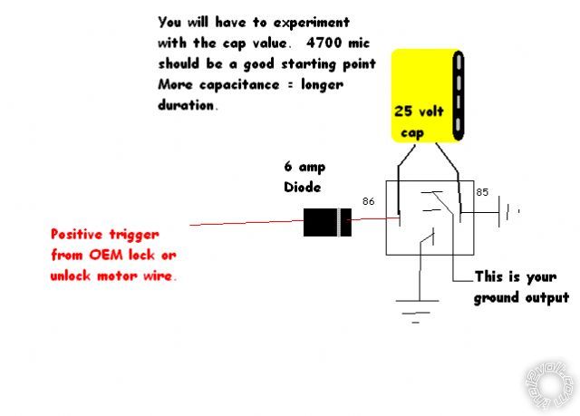
two second ground out without pulse timer -- posted image.
howie ll 
Pot Metal - Posts: 16,466
Pot Metal spacespace
Joined: January 09, 2007
Location: United Kingdom
Posted: October 03, 2009 at 5:49 PM / IP Logged  
Why a 6amp relay?  Is it because of the cap?
i am an idiot 
Platinum - Posts: 13,671
Platinum spaceThis member consistently provides reliable informationspace
Joined: September 21, 2006
Location: Louisiana, United States
Posted: October 03, 2009 at 6:01 PM / IP Logged  
Yes the charging of the cap will take way more than 1 amp of current.  A 3 amp diode will probably be OK, he may have to use 10,000 mic worth of capacitor.  With that much capacitance, a 3 amp diode will probably hold up, but you know I would rather over engineer it than fix it later.
dualsport 
Silver - Posts: 983
Silver spacespace
Joined: September 27, 2005
Location: United States
Posted: October 03, 2009 at 7:52 PM / IP Logged  
The pulse may be too short to charge up the large capacitance needed to hold the relay energized- it really needs a transistor as the relay driver, especially if there's any limitations on the drive signal current. It'll appear as a near short on the signal at the time of the pulse.
i am an idiot 
Platinum - Posts: 13,671
Platinum spaceThis member consistently provides reliable informationspace
Joined: September 21, 2006
Location: Louisiana, United States
Posted: October 03, 2009 at 8:14 PM / IP Logged  
He is using the positive voltage from the door lock solenoid.  I would probably suggest the wrong transistor for the circuit, so how about a diagram? 
Page of 2

  Printable version Printable version Post ReplyPost New Topic
You cannot post new topics in this forum
You cannot reply to topics in this forum
You cannot delete your posts in this forum
You cannot edit your posts in this forum
You cannot create polls in this forum
You cannot vote in polls in this forum

  •  
Search the12volt.com
Follow the12volt.com Follow the12volt.com on Facebook
Friday, May 10, 2024 • Copyright © 1999-2024 the12volt.com, All Rights Reserved Privacy Policy & Use of Cookies
Disclaimer: *All information on this site ( the12volt.com ) is provided "as is" without any warranty of any kind, either expressed or implied, including but not limited to fitness for a particular use. Any user assumes the entire risk as to the accuracy and use of this information. Please verify all wire colors and diagrams before applying any information.

Secured by Sectigo
the12volt.com spacer
Support the12volt.com
Top
the12volt.com spacer