the12volt.com spacer
icon

single switch, multiple outputs


Post ReplyPost New Topic
< Prev Topic Next Topic >
oldspark 
Gold - Posts: 4,913
Gold spacespace
Joined: November 03, 2008
Location: Australia
Posted: September 18, 2010 at 12:22 AM / IP Logged  
I was considering more from the control POV - ie, you shouldn't need more than the 6 relays that switch the power - the logic is done by novel interconnection (eg - the 2 series-grounding relays in my earlier diagram) and maybe diodes.
(Remember - the diodes in my diagram were not "logic" or control diodes, they were to stop "leakage" thru alternate paths. If the loads were LEDs or similar impedances requiring full voltage, they would not be required.)
But a lot depends on the topology.
For example, to "OR" three inputs (either a or b or c turn on the load), in addition to the 3 switches, 3 relays or 3 diodes are needed if it is hot switched (+12V).
But if it is ground switched, only the 3 switches are needed (they are all commoned to ground instead of (different) +12V sources.
FYI - It does seem to annoy people when I replace their complex multiple relays with a polarity change of the control switching and maybe retain 1 or 2 of their birds-nested relays! But I blame that on psychologists and their Bool. single switch, multiple outputs - Page 3 -- posted image.
blowndakrt 
Copper - Posts: 94
Copper spacespace
Joined: March 14, 2008
Location: Iowa, United States
Posted: September 19, 2010 at 11:58 AM / IP Logged  
Ok, I was able to take a look at the car again and get some info.
For the windows, its seems I am not getting 12 volts at the switch themselves, but I do get 12 volts coming out of the small control box that goes to the window motors. So I will probably make my connections after that small control box. That way I can be sure I am getting a full 12 volts to the relays and don't have to worry about affecting the warranty of the control box.
He also brought in the wiring instructions for the power window kit the shop installed. They have a pre-terminated plug on each end that plugs into the window switches and then into that small control box. Since I am not getting a full 12 volts from the switch, I am going to assume they are using data or possibly USB protocol to the control box. Then coming out of the control box, it has the power, ground for the control box, and then the wires going out to the window motors.
Blue/Green   - LF Up    (AC)
Blue/Black   - LF Down (AC)
Green        - RF Up    (AC)
GREEN/ Black - RF Down (AC)
WHITE/ Green - LR Up    (AC)
WHITE/ Black - LR Down (AC)
ORANGE / Green - RR Up    (AC)
ORANGE / Black - RR Down (AC)
Edit: After re-reading, figured I should clarify the above wires. He is not using all 4 windows. He is only using the fronts. I am assuming they send out the same control box for the 2 window kits and the 4 window kits. But his kit only has the 2 window switches.
So I'm thinking that they put (AC) in the diagram to show polarity switching. Would that be correct? I tested each wire they get 12 volts when you hit the rocker in that direction.
For the air bag valves, each valve is getting 12 V momentary to operate out of the switch box. He wants to keep the switch box hooked up as well as it has built in remote control functions. So I am going to assume we will need to use a diode on those so he doesn't accidentally operate another feature through the remote if the switch is not set to that operation.
Now the weird part is the actuators. One is seeing a 12 V momentary for the forward movement and 12 V momentary for the retract movement. That is the hood actuator.
The trunk actuator is seeing a momentary negative pulse for forward movement, and momentary negative pulse for retract. This is because he is using a small actuator controller with programmable stops on both directions. So a single negative pulse on one wire opens the trunk to the predetermined stop, and then a negative pulse on the other wire closes the trunk to the predetermined stop.
He said the shop did it that way because the actuator they used has too much travel, but had to use that size for the weight. Plus they told him it would make it simple to add a trunk pop feature when he installed his alarm later on. Which I agree with.
So with that info, is this going to make the relays and such much more complicated?
Thanks
Shawn
oldspark 
Gold - Posts: 4,913
Gold spacespace
Joined: November 03, 2008
Location: Australia
Posted: September 19, 2010 at 12:55 PM / IP Logged  
Que?
It seems we now have 4 windows instead of one....
You supply a connection diagram of how it it currently configured, plus what you want to control the relays and where those relays are to be added.
We'll take it from there....
i am an idiot 
Platinum - Posts: 13,693
Platinum spaceThis member consistently provides reliable informationspace
Joined: September 21, 2006
Location: Louisiana, United States
Posted: September 19, 2010 at 1:13 PM / IP Logged  
I think Radio Shack sells a 6 position Double pole rotary switch.  I can get you a part number if youi need it.
blowndakrt 
Copper - Posts: 94
Copper spacespace
Joined: March 14, 2008
Location: Iowa, United States
Posted: September 19, 2010 at 3:38 PM / IP Logged  
oldspark wrote:
Que?
It seems we now have 4 windows instead of one....
You supply a connection diagram of how it it currently configured, plus what you want to control the relays and where those relays are to be added.
We'll take it from there....
Yeah after I went back and reread what I had typed, I edited the post to show that we were only using the front windows on his setup. I simply copied exactly what they had on the wire diagram that came with the window kit.
I want to put the relays on the output of the window control box.
Those wires all have 12 volts momentary.
Blue/Green   - LF Up    (AC)
Blue/Black   - LF Down (AC)
Green        - RF Up    (AC)
GREEN/ Black - RF Down (AC)
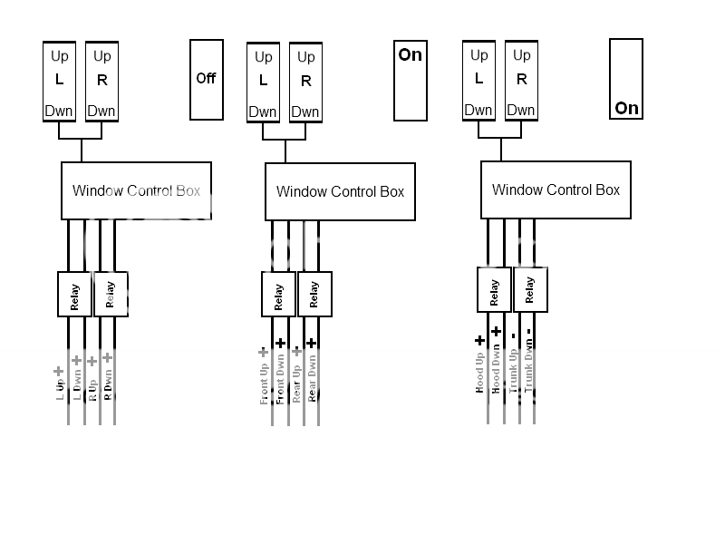
The windows control will be with the latched rocker in the off position.
With the latched rocker in the 1st On position, the 2 switches will simply be momentary 12v to go to the air bag valves.
With the latched rocker in the 2nd On position, one of the window switches , we will say left for example, (up/down) will be momentary 12v for the front hood actuator. The other window switch, we will say right, will be momentary negative (up/down) for the rear actuator going to the actuator control box.
If needed, I can simply do another set of relays to convert to negative polarity for the trunk actuator. But figured I would give the info exactly how it is setup, so that if we can do the negative polarity for the right switch, when in 2nd on position, by wiring up that set of relays different, you would have the info before hand.
Does that make sense?
Here is a quick picture I drew up to show where I want to go with the relays. There are 3 different pictures there to show how I would like each output from the relays with the latched rocker position. It shows the 2 window rockers as well as the latched rocker in the different positions.
I realize it will be more than 2 relays in the total configuration, but just drew 2 for each output to keep it from being cluttered.
Hope that helps convey what I am trying to acheive.
single switch, multiple outputs - Page 3 -- posted image.
Thanks
Shawn
oldspark 
Gold - Posts: 4,913
Gold spacespace
Joined: November 03, 2008
Location: Australia
Posted: September 19, 2010 at 8:45 PM / IP Logged  
The diagram is good.
Just add the the "target" (motors, actuators, valves) with their connections and grounding; and which switches you are adding or using, and how they are powered.
You don't have to worry about the existing window switches if they are not being used. (Although why NOT use the window control box?)
This is very different to what you originally which only involved 3 individual targets.
Make sure you clarify how many windows are being controlled - it was ONE window up/down, bags front/rear, and actuator hood/trunk.
blowndakrt 
Copper - Posts: 94
Copper spacespace
Joined: March 14, 2008
Location: Iowa, United States
Posted: September 19, 2010 at 10:50 PM / IP Logged  
oldspark wrote:
The diagram is good.
Just add the the "target" (motors, actuators, valves) with their connections and grounding; and which switches you are adding or using, and how they are powered.
You don't have to worry about the existing window switches if they are not being used. (Although why NOT use the window control box?)
This is very different to what you originally which only involved 3 individual targets.
Make sure you clarify how many windows are being controlled - it was ONE window up/down, bags front/rear, and actuator hood/trunk.
Sorry, I may have confused you as we went back on forth on some ideas.
In my original post I talked about a set of aftermarket power windows in the vehicle. He wanted to use a separate 3 way latched rocker to allow the factory power window switches to control the other devices.
From my original post "I have a customer that added after market power windows to his car. He has 2 momentary rocker switches (ON)-Off-(ON), but wants to be able to use those same switches to control other things in his car. I tried to figure out how to go about it using a 3 position ON-Off-ON rocker. The problem I keep running into is that when the latched rocker is in the off position, for the power windows to work as normal."
So in essence, we would only be adding a single 3 way latched rocker to his current setup.
My original idea was to put the relays after the power window control box. For one, because I know I am getting 12 volts out of that, and to protect the warranty on his power window kit. Plus the entire idea was to not clutter up the car with more switches. So we were just looking to add the single 3 way latched rocker and use the switches that are already in there for the power windows to control everything.
I just assumed in your diagram you were showing the wiring for a single momentary rocker and I would need to duplicate that for the other switch.
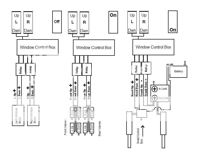
In the diagram I posted, the first one is going to go for the power windows, Left up, Left down, Right Up, Right down. Since the power windows are reversed polarity, it will depend on which direction the motor is going as to which is power and which is ground.
The second diagram is for the air bags. I need a positive momentary that is active as long as the button is held down in the desired direction to activate them as they are grounded at the valve mounts already. Like I said before, I do not want to use the relay on the grounds as it would mean a complete rewire of his entire air system.
And finally the last one is to the linear actuators. For the one actuator I need a positive momentary to the extend wire, and then a positive pulse for the retract wire. Both of those will need to be active as long as the button is held down in the desired direction. I do not need to have them switch polarity.
For the other actuator, I would need a negative momentary for both wires. It does not matter if it is a single pulse or a negative momentary that is active as long as the button is pressed. The actuator controller will work the same with either negative input.
Shawn
blowndakrt 
Copper - Posts: 94
Copper spacespace
Joined: March 14, 2008
Location: Iowa, United States
Posted: September 20, 2010 at 10:40 AM / IP Logged  
Here is the picture with the added devices and how they are hooked up.
single switch, multiple outputs - Page 3 -- posted image.
Thanks
Shawn
blowndakrt 
Copper - Posts: 94
Copper spacespace
Joined: March 14, 2008
Location: Iowa, United States
Posted: September 22, 2010 at 9:40 AM / IP Logged  
So anymore info or ideas on this? Is it going to be possible?
Thanks
Shawn
oldspark 
Gold - Posts: 4,913
Gold spacespace
Joined: November 03, 2008
Location: Australia
Posted: September 22, 2010 at 10:43 AM / IP Logged  
Sorry - I thought there was more coming....
So.... you will add a rocker switch.
In its neutral position (off), windows operate normally.
In one position (on1) the valves are selected (instead of windows).
In the opposite position (on2) the actuators are selected.
The "pulsing" required is down by the switch operator.   
As you have drawn it, the valves are easy.
A DPDT relay for each end (1 front, 1 rear) placed "between" the window motors and the valves.
Contacts #30 to the Window Control Box.
Contacts #87a (NC) to window motors.
Contacts #87 to valves.
Both relay #85s to GND.
Both relay #86s to the added rocker switch's "on1".    
The same should apply to the actuators (not that the window motors are shown with them).
Hence 4 DPDT relays.... ??
Page of 4

  Printable version Printable version Post ReplyPost New Topic
You cannot post new topics in this forum
You cannot reply to topics in this forum
You cannot delete your posts in this forum
You cannot edit your posts in this forum
You cannot create polls in this forum
You cannot vote in polls in this forum

  •  
Search the12volt.com
Follow the12volt.com Follow the12volt.com on Facebook
Thursday, October 31, 2024 • Copyright © 1999-2024 the12volt.com, All Rights Reserved Privacy Policy & Use of Cookies
Disclaimer: *All information on this site ( the12volt.com ) is provided "as is" without any warranty of any kind, either expressed or implied, including but not limited to fitness for a particular use. Any user assumes the entire risk as to the accuracy and use of this information. Please verify all wire colors and diagrams before applying any information.

Secured by Sectigo
the12volt.com spacer
Support the12volt.com
Top
the12volt.com spacer