the12volt.com spacer
icon

python 1401, viper 5101 for 87 mazda rx7


Post ReplyPost New Topic
< Prev Topic Next Topic >
t&t tech 
Platinum - Posts: 2,608
Platinum spacespace
Joined: October 05, 2008
Location: Trinidad and Tobago
Posted: January 04, 2011 at 4:46 PM / IP Logged  

My bad. LOL.

No howard, haven't had the time. Check the general discussion i have a question?

brettlinton7 
Member - Posts: 10
Member spacespace
Joined: January 03, 2011
Location: Georgia, United States
Posted: January 04, 2011 at 10:12 PM / IP Logged  
2 Hatch actuators, the relay for those, 2 more relays for my light flash wire and for my new e-fan, a momentary push button switch for the turbo timer/ cool down mode, and a DEI 451M unit are ordered. Not bad for ~$40.
I will more than likely not have the wiring done until this weekend since this evening was my only free one to work on anything and things came up. And I doubt everything that I ordered will be here before Saturday, so it will probably be the weekend after before I have the unit in working order (hopefully...). I will post back then with the ignition wires listed out and the new wiring order for the 8-pin harness soon. Thanks again for your help.
87 RX7 GXL (DD)
88 RX7 convertible (project)
87 RX7 SE (parts car)
05 Accord (her car)
howie ll 
Pot Metal - Posts: 16,466
Pot Metal spacespace
Joined: January 09, 2007
Location: United Kingdom
Posted: January 05, 2011 at 3:38 AM / IP Logged  
Why a momentary switch for the turbo timer?
Use a timed aux output if there is one.
brettlinton7 
Member - Posts: 10
Member spacespace
Joined: January 03, 2011
Location: Georgia, United States
Posted: January 05, 2011 at 2:22 PM / IP Logged  
howie ll wrote:
Why a momentary switch for the turbo timer?
Use a timed aux output if there is one.
The Viper 5101 install manual said that wire needed a single pulse ground to activate the turbo timer upon manual ignition shut down? Did I read that wrong?
87 RX7 GXL (DD)
88 RX7 convertible (project)
87 RX7 SE (parts car)
05 Accord (her car)
howie ll 
Pot Metal - Posts: 16,466
Pot Metal spacespace
Joined: January 09, 2007
Location: United Kingdom
Posted: January 05, 2011 at 4:04 PM / IP Logged  
If you're talking about adding a relay there's either a dedicated turbo timer out put or you use an aux set to a TIMED pulse of about 11/2 mins.
Does this vehicle even have a turbo?
brettlinton7 
Member - Posts: 10
Member spacespace
Joined: January 03, 2011
Location: Georgia, United States
Posted: January 05, 2011 at 8:53 PM / IP Logged  
It's naturally aspirated, but with any rotary you want to give it time to cool down before shutting off the engine if you've been running it hard. A switch like this would have been great to have for summer mountain runs and Auto-X.
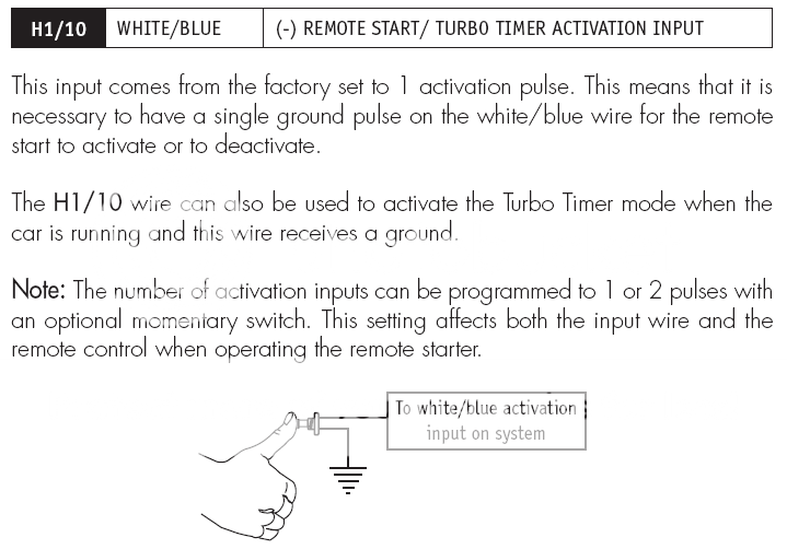
So I'm confused on why I would need a timer/ relay for this. The install manual says that you can install a momentary switch and even has a wiring diagram picture, that's why I specifically bought one. Help?
python 1401, viper 5101 for 87 mazda rx7 - Page 2 -- posted image.
Thanks again.
87 RX7 GXL (DD)
88 RX7 convertible (project)
87 RX7 SE (parts car)
05 Accord (her car)
howie ll 
Pot Metal - Posts: 16,466
Pot Metal spacespace
Joined: January 09, 2007
Location: United Kingdom
Posted: January 06, 2011 at 3:36 AM / IP Logged  
You're right ignore my last comment.
brettlinton7 
Member - Posts: 10
Member spacespace
Joined: January 03, 2011
Location: Georgia, United States
Posted: January 08, 2011 at 10:12 AM / IP Logged  
So I finished the wiring on the remote start and have it working correctly, but I still have not received any of the items I ordered online so it will more than likely be next weekend before I have the keyless entry, cool-down mode, and hatch release working.
Wiring diagram for the remote start soon.
87 RX7 GXL (DD)
88 RX7 convertible (project)
87 RX7 SE (parts car)
05 Accord (her car)
brettlinton7 
Member - Posts: 10
Member spacespace
Joined: January 03, 2011
Location: Georgia, United States
Posted: January 29, 2011 at 12:50 PM / IP Logged  
Completed Wiring Instructions (Let me know if something is listed incorrectly):
Main Harness (12 pin):
1- Trunk release output (RED / white)- connected to 4-pin relay wired to hatch actuators
2- Constant 12v input (red)- connected to (+) battery
3- Horn honk output (brown)- connected GREEN/ orange stripe horn wire on column
4- Light flash insolation (WHITE/ brown)- DISCONNECTED
5- Ground (black)- grounded to chassis
6- (+) door trigger input (violet)- DISCONNECTED
7- Factory horn input (blue)- DISCONNECTED
8- (-) door trigger input (green)- DISCONNECTED
9- Dome light input (BLACK/ light)- DISCONNECTED
10- Turbo timer input (WHITE/ blue)- connected to momentary push button, with other side of switch grounded
11- Parking light output (white)- on + side of hazard button (still have not worked on this one, but plan to wire up to hazard lights, may need a 4-pin relay)
12- Ground when armed output (orange)- DISCONNECTED
Door Lock (3 pin):
Use DEI 451M Relay and plug into here.
DEI 451M Relay:
Purple- connected to (+) battery
Thick Blue- wired to blue wire on door actuators
Thick Green- wired to green wire on door actuators
Brown- grounded to 10MM bolt on the driver side of the transmission tunnel behind the plastic cover on the lower dash
WHITE/ black stripe- grounded " " " " " "
Blue/ GREEN/ Red wires on plug- plugged into Python 3-pin connector
H2 Harness (18 pin):
1- Factory alarm disarm (light GREEN/ black)- DISCONNECTED
2- Aux 4 (ORANGE / black)- DISCONNECTED
3- Factory alarm arm (GREEN / WHITE)- DISCONNECTED
4- Aux 2 (violet/black)- DISCONNECTED
5- Aux 3 (WHITE/ black)- DISCONNECTED
6- Aux 1 (WHITE/ violet)- DISCONNECTED
7- Diesel wait to start (grey/black)- DISCONNECTED
8- empty
9- Tachometer input (violet/white)- tapped into (-) black wire on Trailing on coil
10- Status output (dark blue)- DISCONNECTED
11- Flex relay (pink/white)- DISCONNECTED
12- Accessory output (orange)- DISCONNECTED
13- Starter output (purple)- DISCONNECTED
14- Ignition 1 output (pink)- DISCONNECTED
15- Hood pin input (grey)- connected with provided sensor (I mounted this just above the drivers side headlight. A ~3/8 hole must be drilled)
16- 2nd status/ rear defog (blue/white)- DISCONNECTED
17- (+) brake shutdown input (brown)- tapped into WHITE/ green stripe on brake switch and gets (+) when brake is pressed
18- Neutral safety input (BLACK/ white)- ground to GREEN/ black wire off of tranny (pin G on the ECU) (Thanks Icemark)
Remote Start (8 pin):
1- Ignition input (pink)- on BLACK/ yellow stripe wire that sends (+) to ECU/ etc from ignition
2- Fused ignition 2 (RED / white)- on solid black wire on ignition that receives constant 12v
3- Accessory Output (orange)- connected to solid blue wire on column that powers radio/ wipers/ etc.
4- Starter Output (violet)- on BLACK/ red stripe wire that sends (+) to starter from ignition
5- Fused ignition 1 (red)- on solid black wire on ignition that receives constant 12v
6- Ignition 2/ flex relay (pink/white)- DISCONNECTED
7- Flex relay input (pink/black)- DISCONNECTED
8- Fused accessory/ starter input (RED / black)- on solid black wire on ignition that receives constant 12v
87 RX7 GXL (DD)
88 RX7 convertible (project)
87 RX7 SE (parts car)
05 Accord (her car)
howie ll 
Pot Metal - Posts: 16,466
Pot Metal spacespace
Joined: January 09, 2007
Location: United Kingdom
Posted: January 29, 2011 at 1:15 PM / IP Logged  
Brown horn honk, does the wire you connected it to sound the horn if you ground it through a test light or a DMM?
Not happy about the turbo timer, you have to programme the unit to make that WHITE/ blue Either a turbo timer OR your activation input from the 1401 and unless the green - door trigger is connected to a door trigger you won't be able to programme it.
The pink should have gone to the wire that goes to 12V+ on ignition (not ACC) and stays live during cranking should only be done at the ignition switch loom.
Page of 3

  Printable version Printable version Post ReplyPost New Topic
You cannot post new topics in this forum
You cannot reply to topics in this forum
You cannot delete your posts in this forum
You cannot edit your posts in this forum
You cannot create polls in this forum
You cannot vote in polls in this forum

  •  
Search the12volt.com
Follow the12volt.com Follow the12volt.com on Facebook
Tuesday, May 14, 2024 • Copyright © 1999-2024 the12volt.com, All Rights Reserved Privacy Policy & Use of Cookies
Disclaimer: *All information on this site ( the12volt.com ) is provided "as is" without any warranty of any kind, either expressed or implied, including but not limited to fitness for a particular use. Any user assumes the entire risk as to the accuracy and use of this information. Please verify all wire colors and diagrams before applying any information.

Secured by Sectigo
the12volt.com spacer
Support the12volt.com
Top
the12volt.com spacer