the12volt.com spacer
icon

problems with clutch bypass in 2008 hhr


Post ReplyPost New Topic
< Prev Topic Next Topic >
fogged306 
Member - Posts: 12
Member spacespace
Joined: November 09, 2011
Location: New York, United States
Posted: November 09, 2011 at 5:11 PM / IP Logged  
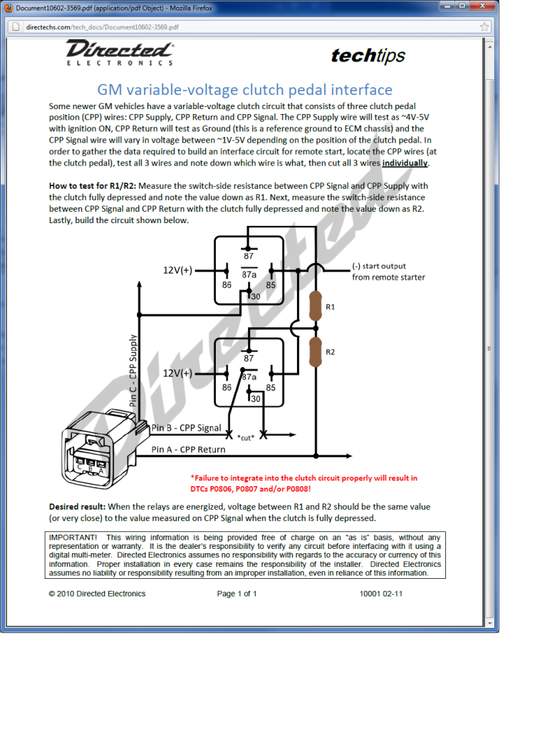
I'm installing a Viper 2-way R/S in a stick 08 HHR and Can't get the clutch bypass to work correctly. I've never seen a variable resistance clutch switch before so this is my first attempt at it. I'm using directed document 10001 for the bypass. I cut all 3 wires and measured resistance between supply and signal wire, and between the return and the signal wire with the clutch fully depressed and used those values as my resistances. I did try this first without cutting the supply and return wires and got different readings than with them cut, so I'm now using the accurate readings of the switch alone with nothing else attached. I've triple checked my wiring and replaced my relays and sockets twice to verify no faulty parts. My resistance is within 10% of the values measured also.
The problem I'm having is when I try to remote start the car the car will only crank for about half a second and stop before the engine actually fires. I've narrowed it down to the clutch bypass because if I disconnect the negative start trigger to the clutch bypass and push the clutch in manually while I remote start, the car will fire and run every time. I've tried varying the resistances a little and the car will go into almost like a timed lockout as if I sent an improper signal to the immobilizer. It wont' let the vehicle start with the key for about 10 minutes or so if I send the wrong resistance through that signal wire on the clutch. It won't let me even start with the key for that time period. It's definitely not the security bypass because like I said, the car will fire and run fine multiple times if I manually engage the clutch and remote start, and I also don't get a flashing or constant illuminated security light. I had to throw in the towel on it and sent it on it's way not finished until I can get some other things to try. That lock out was a bit scary though and I don't want to do any damage to the BCM. I'm an independent shop and I just opened up for business after 12 yrs of working in stereo shops for other people, so I dont' want to have to make an insurance claim right off the bat like this, hah. Any suggestions?
fogged306 
Member - Posts: 12
Member spacespace
Joined: November 09, 2011
Location: New York, United States
Posted: November 09, 2011 at 5:22 PM / IP Logged  
I should also add that this only worked when I modified the diagram in the 10001 document. If you're looking at the diagram, I took R1 and ran it straight to the CPP return instead of running them in series like that. Otherwise, I had almost double the resistance going to the CPP supply than what was actually metered. Maybe I'm mis-interpreting how this is supposed to work, but with out me doing it like that, I would get no crank and the lock-out timer activated every time as it's depicted in the diagram... I've been an installer for long enough to have seen plenty of mistakes in diagrams so I went on a limb here and assumed this may be another one of those.
Another thing I've tried is just using a negative start trigger and a 180 ohm resistor to the signal wire, and that activates the lockout as well.
Here's the techdoc. If this is in-appropriate to post here, mods please feel free to remove it. Not sure what your policy is on that.
problems with clutch bypass in 2008 hhr - Last Post -- posted image.
fogged306 
Member - Posts: 12
Member spacespace
Joined: November 09, 2011
Location: New York, United States
Posted: November 09, 2011 at 5:26 PM / IP Logged  
Can't edit posts yet so one more thing I need to add, lol. When I said "worked" in the post above I was referring to when it actually will allow the R/S to crank, but only for the 1/2 second it does, which isn't long enough to allow the car to fire. Another indication that's its the clutch seeing as how this is an auto-crank vehicle. That's as close as I've come at this point to actually working.
awdeclipse 
Copper - Posts: 285
Copper spacespace
Joined: August 05, 2007
Location: Michigan, United States
Posted: November 10, 2011 at 7:44 AM / IP Logged  
After determining your R1,R2 values did you confirm you are getting the same voltage @ CPP Signal(87a)and CPP-Rtn fully depressed pedal and when you measure at CPP Signal (87) and CPP-Rtn with (85) energized?
This will at least confirm you selected the right resistor values if you have a comparable voltage both ways.
The tech doc is setup as a voltage divider, while R1 and R2 seem in series, you are pulling the CPP Signal wire off from between the two. All you are trying to do here is turn the Variable CPP into a clutch switch by using the fully depressed value the CPP outputs. (same thing the ECU wants for the start)
I would remeasure the resistances, keep in mind the measurements need to be done with the switch removed from the circuit.
fogged306 
Member - Posts: 12
Member spacespace
Joined: November 09, 2011
Location: New York, United States
Posted: November 10, 2011 at 9:48 AM / IP Logged  
Ok, now that you say that and looking over the diagram again, that makes sense. You're pulling the signal in from pin 30 on the r2 relay and splitting that between the supply and the return. So the ECU is actually measuring the voltages on the supply and return as opposed to the signal wire, which the opposite of what I was thinking. Really couldn't wrap my head around how it would have worked the way I was thinking.
No I didn't measure voltage. I did double check my resistances though and did measure with the switch completely removed from the circuit and am 100% positive I'm within 10%.. is it possible that 10% is too far off? I can't remember exact resistances off the top of my head at this point but one was 1.6x and the other was 3.2x and I remember checking to verify 10% or less tolerance. I will check voltages though to be sure. Especially now that I have a better understanding of how that circuit works, I'll better know where to look and what to look for. Appreciate the response.
Any other suggestions? I have to reschedule this and I'm sure this will be my final crack at this before I have to issue a refund so I'd like as many ideas as possible.
awdeclipse 
Copper - Posts: 285
Copper spacespace
Joined: August 05, 2007
Location: Michigan, United States
Posted: November 10, 2011 at 1:10 PM / IP Logged  
ECU/BCM is measuring the voltage of the "signal" wire. It supplies a 5v sensor supply and a reference ground to various sensors and it is measuring the output or the signal wire. Based on the R-values chosen for both sides of the signal wire, you are determining that voltage.
I do not know what the tolerance of that switch is, or what is acceptable from the BCM side. Not sure it is of any help, but I do know that those travel limits have to be learned under certain circumstances. New BCM for example.
I would try the following before trying to come up with another resistor combo:
Using your DMM measure the voltage between CPP Signal and Return. Hold the key in the crank position and start to depress the clutch. When the starter engages note the voltage and the pedal position. Push the clutch all the way to the floor and note that voltage. This will be your voltage tolerance that is acceptable for the vehicle to start. Should help you lean more towards one direction in your resistor selection instead of just 10% as you mentioned.
Also, you said it will start with the pedal pushed in. Make sure you are getting the expected output to PIN 85 on the relays, the start output. You only need something like 200ms on the "crank" wire to initiate the auto start. So if it is not holding the clutch bypass active during the entire crank you will get the same behavior.

Sorry, you can NOT post a reply.
This topic is closed.

  Printable version Printable version Post ReplyPost New Topic
You cannot post new topics in this forum
You cannot reply to topics in this forum
You cannot delete your posts in this forum
You cannot edit your posts in this forum
You cannot create polls in this forum
You cannot vote in polls in this forum

  •  
Search the12volt.com
Follow the12volt.com Follow the12volt.com on Facebook
Thursday, May 16, 2024 • Copyright © 1999-2024 the12volt.com, All Rights Reserved Privacy Policy & Use of Cookies
Disclaimer: *All information on this site ( the12volt.com ) is provided "as is" without any warranty of any kind, either expressed or implied, including but not limited to fitness for a particular use. Any user assumes the entire risk as to the accuracy and use of this information. Please verify all wire colors and diagrams before applying any information.

Secured by Sectigo
the12volt.com spacer
Support the12volt.com
Top
the12volt.com spacer