the12volt.com spacer
icon

compustar cm6000, drone, evo-all


Post ReplyPost New Topic
< Prev Topic Next Topic >
masber2000 
Member - Posts: 32
Member spacespace
Joined: December 03, 2011
Location: Washington, United States
Posted: January 21, 2012 at 7:18 AM / IP Logged  
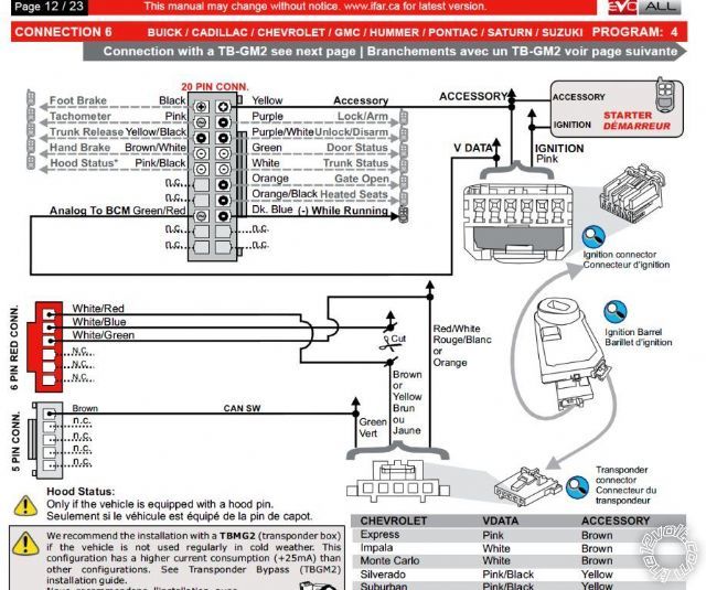
This is the connection procedure I'm using from the EVO-ALL manual:
compustar cm6000, drone, evo-all - Page 2 -- posted image.
kreg357 
Platinum - Posts: 7,783
Platinum spaceThis member has made a donation to the12volt.com. Click here for more info.spaceThis member has been recognized as an authority in Electrical Theory. Click here for more info.spaceThis member has been recognized as an authority in Mobile Security and Convenience. Click here for more info.spacespace
Joined: January 30, 2009
Location: Pennsylvania, United States
Posted: January 21, 2012 at 8:16 AM / IP Logged  

The EVO-ALL (-) While Running Dark Blue connects to the CM6000 CN3 Pin 11, Black (-) 250mA Status Out.

The EVO-ALL Accessory Yellow wire connects to the CM6000 CN1 thick White Accessory wire

which continues to the trucks Accessory wire ( Brown or Yellow ) at the ignition switch or BCM.

The CM6000 only provides one AUX output ( Violet wire at CN3 Pin 19 ).  You can use this for

the Gate Open.  If you had the OP-500 programmer you could program one of the unused POC's
( in the Special Option Groups ) for AUX2 and use that for the Heated Seats control.

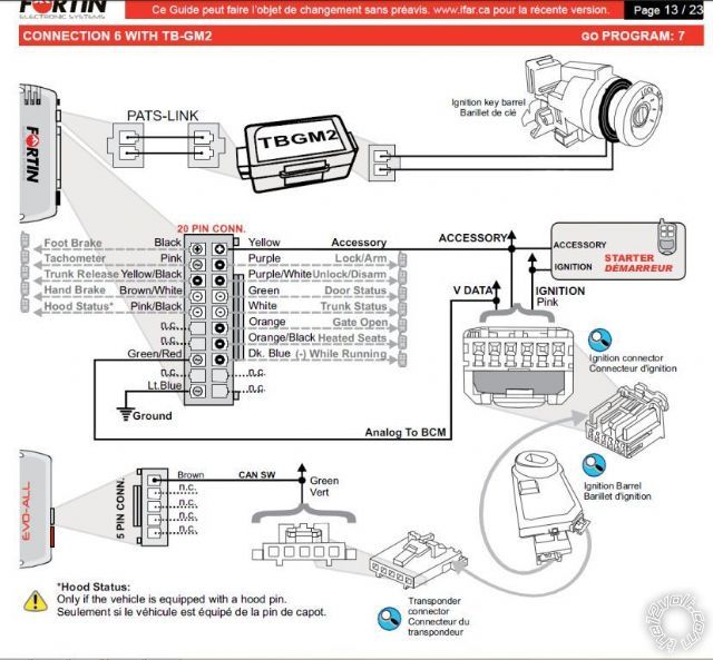
Also note that in this install configuration ( without the TB-GM2 ), the R/S unit will draw an additional

25mA at rest.  If the vehicle is used frequently and has a good battery, you shouldn't have a problem.

Soldering is fun!
masber2000 
Member - Posts: 32
Member spacespace
Joined: December 03, 2011
Location: Washington, United States
Posted: January 21, 2012 at 8:42 AM / IP Logged  
My apologies kreg357, I posted the wrong connection! You are correct. I've posted the correct one below. I will update and post the new wiring spreadsheet with your inputs for review asap.
compustar cm6000, drone, evo-all - Page 2 -- posted image.
masber2000 
Member - Posts: 32
Member spacespace
Joined: December 03, 2011
Location: Washington, United States
Posted: January 21, 2012 at 9:53 AM / IP Logged  
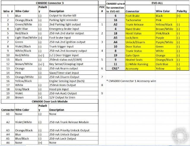
Attached is my wiring chart with the suggestions from kreg357 (thank you kindly kreg357). Is this the correct wiring plan?
Thank you
compustar cm6000, drone, evo-all - Page 2 -- posted image.
kreg357 
Platinum - Posts: 7,783
Platinum spaceThis member has made a donation to the12volt.com. Click here for more info.spaceThis member has been recognized as an authority in Electrical Theory. Click here for more info.spaceThis member has been recognized as an authority in Mobile Security and Convenience. Click here for more info.spacespace
Joined: January 30, 2009
Location: Pennsylvania, United States
Posted: January 21, 2012 at 10:23 AM / IP Logged  

Looks OK with the possible exception of the EVO-ALL Heated Seats wire going to the CM6000

(-) Acc output.  Not sure if the EVO-ALL is looking for a single (-) pulse to turn on/off
the seats or a constant (-) to run the seat heaters.  If it does work, then perhaps a switch
in the wire connection for winter/summer operation?

Other connections :

CM6000 CN3 Pin 3 GREEN / WHITE to PARKING LIGHTS ( - )   LT. BLUE (-)    @ HEADLIGHT SWITCH

CM6000 CN1 Pin 4 Black to Chassis Ground

CM6000 CN1 Pin 5 Red x 2 to +12V constant ( Battery )

CM6000 CN1 Pin 3 Green to IGNITION 1   PINK (+)    @ IGNITION Harness

CM6000 CN1 Pin 1 White to ACCESSORY /HEATER BLOWER 1   BROWN or YELLOW (+)    @ IGNITION Harness

Soldering is fun!
masber2000 
Member - Posts: 32
Member spacespace
Joined: December 03, 2011
Location: Washington, United States
Posted: January 21, 2012 at 12:34 PM / IP Logged  
Thank you very much kreg357!
masber2000 
Member - Posts: 32
Member spacespace
Joined: December 03, 2011
Location: Washington, United States
Posted: January 23, 2012 at 10:14 PM / IP Logged  
Ok, another question lol.
I'm preparing the wires for the 520T backup battery. The DEI installation instructions says to make two connections to the CM6000; the (+) constant power12V and the (-) instant trigger. While I've made the power connection between the two, I am unsure of the CM6000 wire that connects to the (-) instant trigger. The CM6000 has a distinct connection for the backup battery, however, the there's no instant trigger wire on the CM6000, only a ground wire. Thus I need to connect to another CM6000 that will provide the instant trigger function. Any idea on the wire I should use to make the connection with the 520T?
Regards
masber2000
tedmond 
Gold - Posts: 4,610
Gold spaceThis member has been recognized as an authority in Mobile Security and Convenience. Click here for more info.spacespace
Joined: January 06, 2007
Location: Ontario, Canada
Posted: January 23, 2012 at 10:39 PM / IP Logged  
connect that to a hood or door pin. diode isolate.
that just tells the cm6000 a trigger occurred. if you want to be extra, connect to the cm6000 4pin green connection 13
connect the trigger wire from the 520t to the white wire in the 4pin green plug into the cm6000 (connector 13)
Ted
2nd Year Tier 1 Medical School
Still installing as a hobby...pays for groceries
Compustar Expert
masber2000 
Member - Posts: 32
Member spacespace
Joined: December 03, 2011
Location: Washington, United States
Posted: January 24, 2012 at 4:58 AM / IP Logged  
thank you tedmond.
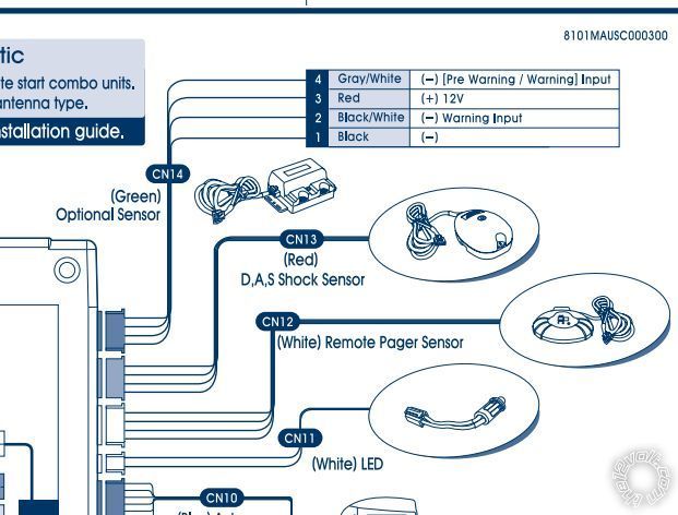
Am I looking at the wrong schematic? I want to tie the trigger wire to connector 13. However, I'm showing the connector 13 as red (the shock sensor), with the 4-pin green connector being CN14 (see diagram below). Do I not have the most recent schematics?
Also, what is the difference between connecting the trigger wire to the hood pin, to connecting it to the white wire on CN13?
compustar cm6000, drone, evo-all - Page 2 -- posted image.
Thanks again
tedmond 
Gold - Posts: 4,610
Gold spaceThis member has been recognized as an authority in Mobile Security and Convenience. Click here for more info.spacespace
Joined: January 06, 2007
Location: Ontario, Canada
Posted: January 24, 2012 at 7:32 AM / IP Logged  
woops, its actually CN14. connect to BLACK/ white.
been a long time since i've used that green connector.
Ted
2nd Year Tier 1 Medical School
Still installing as a hobby...pays for groceries
Compustar Expert
Page of 7

  Printable version Printable version Post ReplyPost New Topic
You cannot post new topics in this forum
You cannot reply to topics in this forum
You cannot delete your posts in this forum
You cannot edit your posts in this forum
You cannot create polls in this forum
You cannot vote in polls in this forum

  •  
Search the12volt.com
Follow the12volt.com Follow the12volt.com on Facebook
Monday, April 29, 2024 • Copyright © 1999-2024 the12volt.com, All Rights Reserved Privacy Policy & Use of Cookies
Disclaimer: *All information on this site ( the12volt.com ) is provided "as is" without any warranty of any kind, either expressed or implied, including but not limited to fitness for a particular use. Any user assumes the entire risk as to the accuracy and use of this information. Please verify all wire colors and diagrams before applying any information.

Secured by Sectigo
the12volt.com spacer
Support the12volt.com
Top
the12volt.com spacer