the12volt.com spacer
icon

02 Pontiac Grand Prix, Viper 5704


Post ReplyPost New Topic
< Prev Topic Next Topic >
alexp1289 
Copper - Posts: 96
Copper spacespace
Joined: July 28, 2012
Location: New Hampshire, United States
Posted: August 25, 2012 at 1:10 PM / IP Logged  
Also does it matter where I hook up the main Power for the alarm? doesn't have to be hooked up directly to the battery or can I choose any 12 volt constant wire? And then ground it to somewhere in the dash? I'm just not sure if or what wires will always be powered on even if the cars not when it's locked. sorry for the simple questions but I just want to make sure I don't make any mistakes the first time.
howie ll 
Pot Metal - Posts: 16,466
Pot Metal spacespace
Joined: January 09, 2007
Location: United Kingdom
Posted: August 25, 2012 at 1:39 PM / IP Logged  
Red and RED / white at ignition loom, split the load, i.e. 2 to one and 2 to the other.
If you enjoy removing the seats fine, NOT if there are built in air-bags.
alexp1289 
Copper - Posts: 96
Copper spacespace
Joined: July 28, 2012
Location: New Hampshire, United States
Posted: August 26, 2012 at 3:27 PM / IP Logged  
Does anybody have a diagram for the satellite relay? And which way do the diodes go?
alexp1289 
Copper - Posts: 96
Copper spacespace
Joined: July 28, 2012
Location: New Hampshire, United States
Posted: August 26, 2012 at 3:32 PM / IP Logged  
The 10 pin connector has a flex relay already on it isn't that the same thing?
alexp1289 
Copper - Posts: 96
Copper spacespace
Joined: July 28, 2012
Location: New Hampshire, United States
Posted: August 26, 2012 at 4:28 PM / IP Logged  
This is all I need help on I need more details.
kreg357 
Platinum - Posts: 7,783
Platinum spaceThis member has made a donation to the12volt.com. Click here for more info.spaceThis member has been recognized as an authority in Electrical Theory. Click here for more info.spaceThis member has been recognized as an authority in Mobile Security and Convenience. Click here for more info.spacespace
Joined: January 30, 2009
Location: Pennsylvania, United States
Posted: August 26, 2012 at 7:28 PM / IP Logged  

Not sure what you mean by "satellite relay".  If you are referring to the extra relay

for the cars Brown ACC2 wire, it was given previously.
ACC2 external relay ( 30/40 Amp SPDT ) if needed  :
Relay Pin 85 to ORANGE (-) 200mA ACCESSORY OUTPUT ( from Viper )
Relay Pin 86 and 87 to +12V constant fused at 20 Amps
Relay Pin 30 to Brown ACC2 wire at Grand Prix Ignition Harness
Relay Pin 87A not used - insulate
The 1N400x diode would be added between Relay Pins 86 and 85 with the band towards Pin 86.

If you are referring to the Vipers Flex relay that will be used for the cars IGN2 wire,

it was included in the previously listed Viper H3 wire connections :
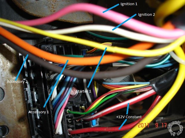
Viper H3 harness wires              2002 Pontiac Grand Prix Ignition Harness
H3/1 PINK (+) IGNITION 1 INPUT/OUTPUT           Pink
H3/2 RED / WHITE (+) FUSED (30A) IGN 2 / FLEX RELAY INPUT 87        Red ( or RED / White )
H3/3 ORANGE (+) ACCESSORY OUTPUT Orange
H3/4 VIOLET (+) STARTER OUTPUT (CAR SIDE)            Yellow
H3/5 GREEN (+) STARTER INPUT (KEY SIDE)                  Yellow
H3/6 RED (+) FUSED (30A) IGNITION 1 INPUT     Red  ( or RED / White )
H3/7 PINK/WHITE (+) IGNITION 2 / FLEX RELAY OUTPUT          White
H3/8 PINK/BLACK (+) FLEX RELAY INPUT 87A  FLEX RELAY                N.U.
H3/9 RED / BLACK (+) FUSED (30A) ACC/STARTER INPUT          Red  ( or RED / White )
H3/10 NC (no connection)  NC

Here is a picture of a generic GM vehicle with similar wires / colors in the ignition harness :

02 Pontiac Grand Prix, Viper 5704 - Page 5 -- posted image.

Soldering is fun!
alexp1289 
Copper - Posts: 96
Copper spacespace
Joined: July 28, 2012
Location: New Hampshire, United States
Posted: August 26, 2012 at 7:31 PM / IP Logged  
I thought you said something about using diodes on 1 of the wires or else I will throw transmission trouble codes? that's on trying to figure out is the specific send anything that I can look at to make it easier to understand.
kreg357 
Platinum - Posts: 7,783
Platinum spaceThis member has made a donation to the12volt.com. Click here for more info.spaceThis member has been recognized as an authority in Electrical Theory. Click here for more info.spaceThis member has been recognized as an authority in Mobile Security and Convenience. Click here for more info.spacespace
Joined: January 30, 2009
Location: Pennsylvania, United States
Posted: August 26, 2012 at 7:34 PM / IP Logged  
Not sure but I think that info came from Howard. 
Soldering is fun!
howie ll 
Pot Metal - Posts: 16,466
Pot Metal spacespace
Joined: January 09, 2007
Location: United Kingdom
Posted: August 27, 2012 at 1:48 AM / IP Logged  
I might have had the wrong info, it may have been Ford vans! On my original diagram I showed the diodes in-line with the orange to 85 rather than across the relay coil.
In practise I do both.
howie ll 
Pot Metal - Posts: 16,466
Pot Metal spacespace
Joined: January 09, 2007
Location: United Kingdom
Posted: August 27, 2012 at 1:50 AM / IP Logged  
OP diodes were to quench relay back EMF nothing to do with DTCs.
Page of 17

  Printable version Printable version Post ReplyPost New Topic
You cannot post new topics in this forum
You cannot reply to topics in this forum
You cannot delete your posts in this forum
You cannot edit your posts in this forum
You cannot create polls in this forum
You cannot vote in polls in this forum

  •  
Search the12volt.com
Follow the12volt.com Follow the12volt.com on Facebook
Saturday, April 27, 2024 • Copyright © 1999-2024 the12volt.com, All Rights Reserved Privacy Policy & Use of Cookies
Disclaimer: *All information on this site ( the12volt.com ) is provided "as is" without any warranty of any kind, either expressed or implied, including but not limited to fitness for a particular use. Any user assumes the entire risk as to the accuracy and use of this information. Please verify all wire colors and diagrams before applying any information.

Secured by Sectigo
the12volt.com spacer
Support the12volt.com
Top
the12volt.com spacer