the12volt.com spacer
icon

02 Pontiac Grand Prix, Viper 5704


Post ReplyPost New Topic
< Prev Topic Next Topic >
kreg357 
Platinum - Posts: 7,789
Platinum spaceThis member has made a donation to the12volt.com. Click here for more info.spaceThis member has been recognized as an authority in Electrical Theory. Click here for more info.spaceThis member has been recognized as an authority in Mobile Security and Convenience. Click here for more info.spacespace
Joined: January 30, 2009
Location: Pennsylvania, United States
Posted: September 18, 2012 at 6:14 PM / IP Logged  

Never be in a hurry.  "Haste makes waste."  You only want to do this project once.

No, none of the Vipers H3 heavy gauge wires go to the PassKey3 connector.

However one of the XK05 wires can go to the H3 harness.

XK05       Destination

Brown     GWR        Viper Blue (-) 200mA Status Output
Red         +12V Constant    Viper Red ( or RED / White or RED / Black )

The rest ( Green, Black, Pink, Pink/White ) get connected to the G.P. PassKey3 connector at the ignition switch.  

Almost done.  02 Pontiac Grand Prix, Viper 5704 - Page 9 -- posted image.

Soldering is fun!
alexp1289 
Copper - Posts: 96
Copper spacespace
Joined: July 28, 2012
Location: New Hampshire, United States
Posted: September 18, 2012 at 6:55 PM / IP Logged  
I was looking at the viper wires and there names on the sheet that came with the alarm and noticed there's a rear defogger/2nd status (-) 200mA output. Can I connect that to my rear defogger button in the front of my car so my rear window is clear in the winter? If not how do I do that?
alexp1289 
Copper - Posts: 96
Copper spacespace
Joined: July 28, 2012
Location: New Hampshire, United States
Posted: September 20, 2012 at 5:58 PM / IP Logged  
Hey guys I've done some wire testing to verify the correct wires and just wanted to have someone look at my results before I solder.
Light blue- lock wire (stays at zero and jumps when locking with OEM remote and switch) usually jumps to 0.10 but it jumps even when unlocking to 0.07 but never any higher :-\
White unlock wire- always reads 12.22 and drops when unlocking and lock button are pressed.
My dmm is set to 20dcv and black lead into COM and red in V. I'm kinda confused here. Also my trunk BLACK/ white wire reads 12.00 when the button is pressed so I'm almost certain I'm doing this correctly :-(
alexp1289 
Copper - Posts: 96
Copper spacespace
Joined: July 28, 2012
Location: New Hampshire, United States
Posted: September 20, 2012 at 8:15 PM / IP Logged  
Really no one can help?
kreg357 
Platinum - Posts: 7,789
Platinum spaceThis member has made a donation to the12volt.com. Click here for more info.spaceThis member has been recognized as an authority in Electrical Theory. Click here for more info.spaceThis member has been recognized as an authority in Mobile Security and Convenience. Click here for more info.spacespace
Joined: January 30, 2009
Location: Pennsylvania, United States
Posted: September 20, 2012 at 9:04 PM / IP Logged  

The correct way to test for your Lock and Unlock wires is as follows:

Set the DMM to 20 VDC.  Connect the Red lead to +12V constant and the Black lead to the suspect

wire.  When the signal is present ( either lock or unlock ) to DMM will show +12V.

This DMM setup and testing method works on wires that are noted as (-) signals.

On some vehicles you might have to use ( turn ) the key in the door cylinder to obtain the signal
and locate / verify the correct wire.

To locate the Trunk Release wire, which is a (+) signal, set the DMM to 20 VDC, connect the

Black lead to chassis ground and the Red lead to the suspect wire.  When the signal is present,
the DMM will show +12V.

This DMM setup and testing method works on wires that are noted as (+) signals.

Soldering is fun!
alexp1289 
Copper - Posts: 96
Copper spacespace
Joined: July 28, 2012
Location: New Hampshire, United States
Posted: September 20, 2012 at 9:14 PM / IP Logged  
Oh ok. I was using the black lead to chassis ground method to find out the right lock wire. Had no idea there was a different way for the lock wire lol.. sry guys (I looked at other threads on here to see if anyone else mentioned the correct way before asking I swear...I kept going wth on the lock wire cause it was reading weird lol). If you guys wouldn't mind, could someone give me a lesson on why there are 2 different testing methods?
kreg357 
Platinum - Posts: 7,789
Platinum spaceThis member has made a donation to the12volt.com. Click here for more info.spaceThis member has been recognized as an authority in Electrical Theory. Click here for more info.spaceThis member has been recognized as an authority in Mobile Security and Convenience. Click here for more info.spacespace
Joined: January 30, 2009
Location: Pennsylvania, United States
Posted: September 20, 2012 at 10:33 PM / IP Logged  

There are two different testing set-ups because there are two basic logic levels

used in vehicle circuits that you will be testing / identifying.

Prior to Multi-plex circuits and Data ( CAN Bus ) circuits all cars used the two voltage

levels supplied by the cars battery to control its power accessories.  The two levels are
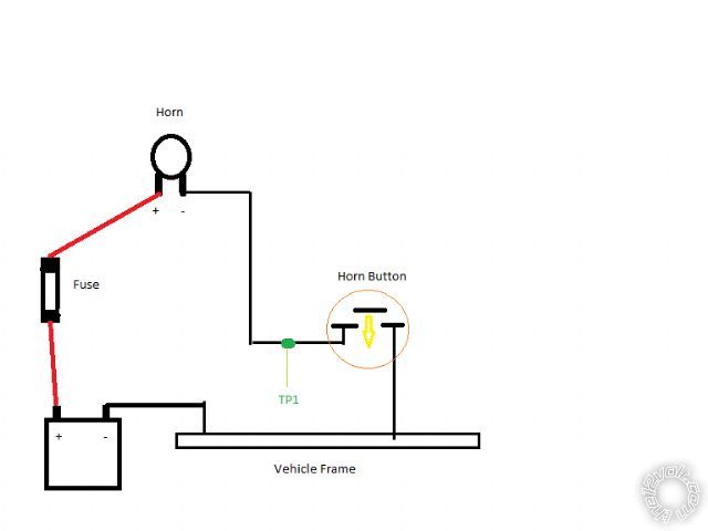
+12V and ground.  We can use a very simple Horn circuit as an example ( no power relay ). 

Battery power, +12V is run thru a protective fuse and to one side of the horn.  The other

side of the horn is wired to the horn button in the steering wheel.  The horn button is a
simple momentary contact switch, normally in the OFF or open position.  The other side of
the horn switch is wired to chassis ground.  When the horn button is depressed, it makes a
connection from the horn thru the switch which is wired to chassis ground.  Chassis ground
is the entire metal frame of the vehicle.  The negative lead of the battery is connected to
the vehicles frame.  While the horn is receiving constant +12V power it will not beep until
the circuit is completed by depressing the horn button ( and completing the path back to the
battery thru the metal chassis ).

02 Pontiac Grand Prix, Viper 5704 - Page 9 -- posted image.

In the horn circuit above, the R/S system would supply a (-) output signal to TP1 to allow

the R/S system to beep the horn.  This wire at TP1 would be listed as a (-) signal in the
vehicles wiring guide.  When using a DMM to locate / verify this wire, it would be set to
20V DC.  The Red lead would be connected to +12V ( battery positive terminal ) and the Black
lead would be connected to TP1.  When the horn button is depressed the DMM would read +12V
because its' Red lead is connected to the batteries positive terminal and the Black lead is
now connected to chassis ground ( aka the batteries negative terminal ) thru the horn button.

Soldering is fun!
howie ll 
Pot Metal - Posts: 16,466
Pot Metal spacespace
Joined: January 09, 2007
Location: United Kingdom
Posted: September 21, 2012 at 1:26 AM / IP Logged  
And here is the number one reason why I use a test light!
Throw over the catch at the rear of the driver door, close all other doors, ground the clip end of the Snap-On CT-42 or MAC equivalent*, probe the other end to each suspected wire and you will activate the lock and unlock if you have the correct wires. It's that simple.
You'll drive yourself mad with those meter readings.
* Or even a marker light with it's attached wires from a wreck.
One side to ground other to suspect wires.
howie ll 
Pot Metal - Posts: 16,466
Pot Metal spacespace
Joined: January 09, 2007
Location: United Kingdom
Posted: September 21, 2012 at 1:29 AM / IP Logged  
And yes I know I'm going to get adverse comments BUT were talking about simple voltage (as explained by Kregg) devices here.
A test light is faster, easier to use and actuates the locks.
alexp1289 
Copper - Posts: 96
Copper spacespace
Joined: July 28, 2012
Location: New Hampshire, United States
Posted: September 21, 2012 at 9:19 PM / IP Logged  
I couldn't agree more Howie. I went out and purchased a bulb tester for $7 I got home and clipped the clip to chassis ground and started probing wires (poked them actually). After 5 minutes of being on my back inside the kick panel while poking multiple light blue and white wires I found them both :-P Best $7 I ever spent for a tester. Like Howie said the car locked and unlocked when I poked the correct wires :-D
Page of 17

  Printable version Printable version Post ReplyPost New Topic
You cannot post new topics in this forum
You cannot reply to topics in this forum
You cannot delete your posts in this forum
You cannot edit your posts in this forum
You cannot create polls in this forum
You cannot vote in polls in this forum

  •  
Search the12volt.com
Follow the12volt.com Follow the12volt.com on Facebook
Wednesday, May 22, 2024 • Copyright © 1999-2024 the12volt.com, All Rights Reserved Privacy Policy & Use of Cookies
Disclaimer: *All information on this site ( the12volt.com ) is provided "as is" without any warranty of any kind, either expressed or implied, including but not limited to fitness for a particular use. Any user assumes the entire risk as to the accuracy and use of this information. Please verify all wire colors and diagrams before applying any information.

Secured by Sectigo
the12volt.com spacer
Support the12volt.com
Top
the12volt.com spacer