the12volt.com spacer
icon

2003-2006 GMC Yukon Remote Start Pictorial


Post ReplyPost New Topic
< Prev Topic Next Topic >
kreg357 
Platinum - Posts: 7,783
Platinum spaceThis member has made a donation to the12volt.com. Click here for more info.spaceThis member has been recognized as an authority in Electrical Theory. Click here for more info.spaceThis member has been recognized as an authority in Mobile Security and Convenience. Click here for more info.spacespace
Joined: January 30, 2009
Location: Pennsylvania, United States
Posted: December 17, 2012 at 6:31 PM / IP Logged  

This is a pictorial for a DIY remote start with keyless entry on a 2003 GMC Yukon.  The 2003 - 2006 model

years are the same.

This is a popular vehicle and similar to many within GM.  Other similar vehicles include the 2003 - 2006 Chevrolet Tahoe,

Chevrolet Silverado, Suburban & GMC Sierra, 2003 - 2004 Cadillac Escalade and some others. 

There are many bypass modules available, from basic Passlock2 only to full featured modules.  While the Passlock2 is

easy to bypass with the old, reliable, relays and resistor method, the power door locks make a full featured bypass module
very attractive.  The bonus features like automatic heated seat and defroster activation make the choice easier.  Popular
bypass choices for the DIY'er include the DEI GMDLBP, the Fortin EVO-ALL, INT-SL and INT-SL+ and from  iDatalink the
ADS DLSL GM1.   Each module has its' own strengths and weaknesses and, depending on the vehicles options, some are
more appropriate than others.

These vehicles do not have "one touch starting" but do have built in anti-grind.  Some vehicles have the optional Factory

Alarm, heated seats, etc.   Originally plan was to install a Compustar CM4200 and the DEI GMDLPB bypass module, shown
bench prepped below. 

2003-2006 GMC Yukon Remote Start Pictorial -- posted image.

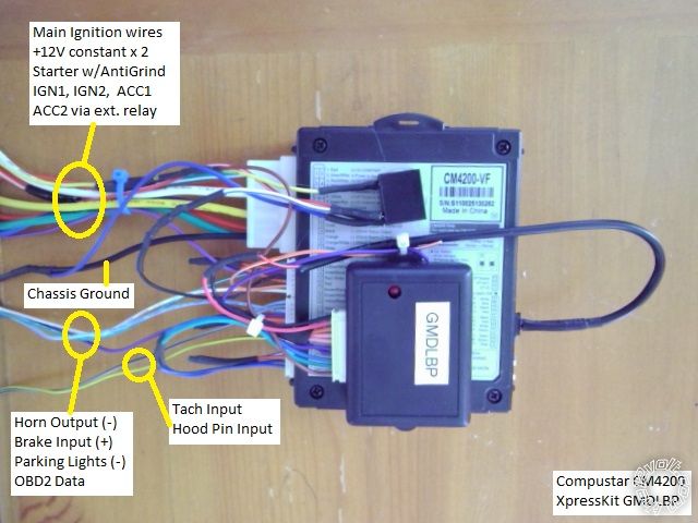
While this is a system is a solid performer, due to the bypass module it would not have handled this vehicles heated

accessories, so the customer opted for the upgrade system pictured below.

2003-2006 GMC Yukon Remote Start Pictorial -- posted image.

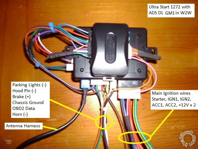
The ADS DL with GM1 firmware bypass module was chosen for this install.  It handles the Passlock2, locks and Factory

Alarm ( if present ) and provides a Tach signal.  Thru Data, it turns on the heated accessories during a remote start if the
engine temp is below 32 degrees.   For Alarm installs, it also provides front door status trigger.
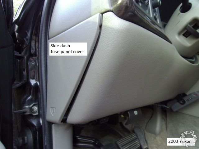
Disassembly :

Remove the side dash fuse box cover by pulling it out at the bottom edge.  This will allow easy antenna harness routing

to the windshield.

2003-2006 GMC Yukon Remote Start Pictorial -- posted image.

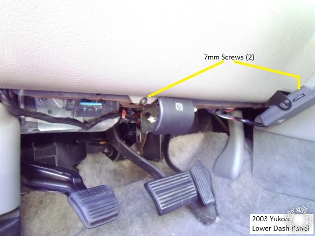
Remove the two 7mm screws shown below and pull the lower dash panel straight away at the top.  There are two clips

along the top edge.

2003-2006 GMC Yukon Remote Start Pictorial -- posted image.

There is no need to remove the steering column cover.  Remove the knee brace to expose the BCM and ignition harness

by removing the four 10mm nuts indicated.

2003-2006 GMC Yukon Remote Start Pictorial -- posted image.

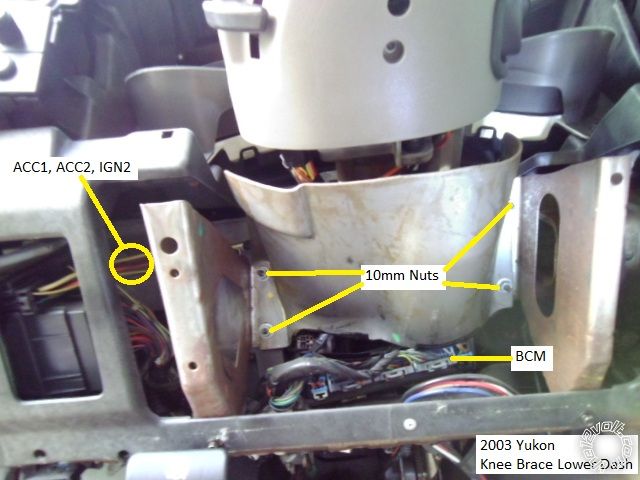
Here is a picture  of the exposed wires after the knee brace is off.

2003-2006 GMC Yukon Remote Start Pictorial -- posted image.

Wiring :

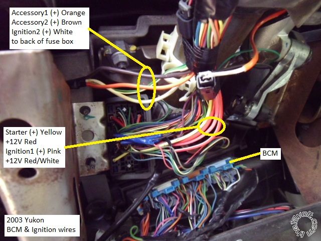
Below is a picture of the thick main ignition wires coming down from the steering column.  Notice they split-up with 3 wires

going to the back of the fuse box.  Plan the R/S wire routing to allow for the knee brace re-installation.  Space is limited and
there is a real need for wire loom protection in this area to prevent wire chaffing against the metal knee plate.  Please remember
to connect the White wire as IGN2 wire or error codes and transmission problems will occur.

2003-2006 GMC Yukon Remote Start Pictorial -- posted image.

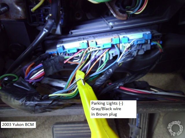
Here is a photo of the BCM with the Parking Light (-) wire marked.  There is a (+) Parking Light wire, but why use it when the

(-) Parking Light wire is so convenient at the BCM.  If installing an alarm system, the two rear door triggers are found in the
BCMs' Purple plug.

2003-2006 GMC Yukon Remote Start Pictorial -- posted image.

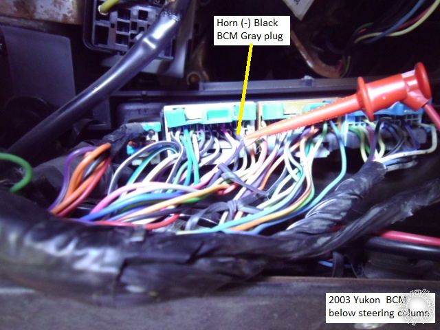
This is a shot of the ( optional ) Horn (-) wire at the BCM.

2003-2006 GMC Yukon Remote Start Pictorial -- posted image.

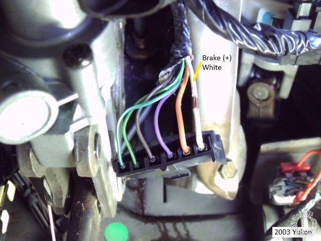
This is a picture of the Brake (+) in the brake pedal switch connector ( unplugged ).  Please note that this brake switch moves

with the pedal and allowances should be made when routing, connecting and securing this R/S wire.

2003-2006 GMC Yukon Remote Start Pictorial -- posted image.

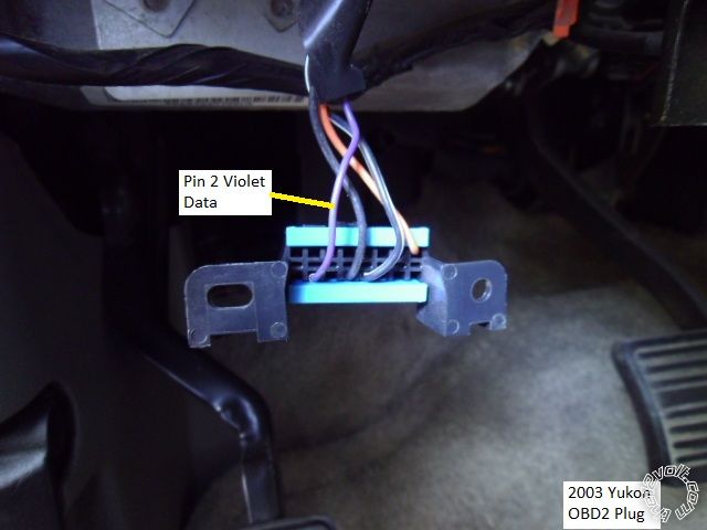
Here is a picture of the OBD2 diagnostic connector and its' Purple Data wire at Pin 2.

2003-2006 GMC Yukon Remote Start Pictorial -- posted image.

There are many locations to connect the R/S Chassis Ground wire under the dash.  Firewall pass-thru for the Hood Pin is

found at the main wire harness behind the parking brake assy.  As always, use a Digital Multi Meter to locate, test and verify
all vehicle wires prior to making a quality solder connection.

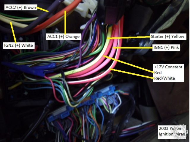
This style vehicle typifies many GM's from around this time period.  With Passlock2, a convenient BCM under the steering

column and the GM standard ignition wire colors of :  Red & RED / White for +12V constant, Yellow for Starter, Pink for IGN1
and White for IGN2, Orange for ACC1 and Brown for ACC2.

Soldering is fun!
shortcircuit161 
Silver - Posts: 556
Silver spaceThis member has made a donation to the12volt.com. Click here for more info.spacespace
Joined: August 29, 2010
Location: United States
Posted: December 18, 2012 at 8:55 AM / IP Logged  
Very nice!!! That's a very popular setup. Looks just like the Escalade and Silverado I did recently.
jaimejr18 
Member - Posts: 26
Member spacespace
Joined: February 24, 2013
Location: Texas, United States
Posted: March 01, 2013 at 5:38 PM / IP Logged  
how yu wire the locks and unlocj to work with the alarm
kreg357 
Platinum - Posts: 7,783
Platinum spaceThis member has made a donation to the12volt.com. Click here for more info.spaceThis member has been recognized as an authority in Electrical Theory. Click here for more info.spaceThis member has been recognized as an authority in Mobile Security and Convenience. Click here for more info.spacespace
Joined: January 30, 2009
Location: Pennsylvania, United States
Posted: March 01, 2013 at 6:55 PM / IP Logged  

"There are many bypass modules available, from basic Passlock2 only to full featured modules.  While the Passlock2 is

easy to bypass with the old, reliable, relays and resistor method, the power door locks make a full featured bypass module
very attractive.  The bonus features like automatic heated seat and defroster activation make the choice easier.  Popular
bypass choices for the DIY'er include the DEI GMDLBP, the Fortin EVO-ALL, INT-SL and INT-SL+ and from  iDatalink the
ADS DLSL GM1.   Each module has its' own strengths and weaknesses and, depending on the vehicles options, some are
more appropriate than others."

The easy way is using a full featured bypass module like the ones mentioned above.  ( The front doors are controlled by

a Data type signal, the rears are Type B.)  Being as you need a bypass module for the Passlock2 ignition immobilizer
system, for a few extra dollars you can get a bypass module that will do the door locks, factory alarm, heated seats
and rear defroster and supply a Tach signal and front door pin status.  For this install, all of this was handled by the
bypass modules one connection to the Violet wire at Pin 2 of the OBD2 connector.

Doing everything with relays would require going into both front doors and a total of 6 relays.  Here is a link to DEI

Tech Tip 1601 :  https://www.the12volt.com/installbay/file.asp?ID=828    And you would still need to bypass the
Passlock2 system.

Here is a link to a current, DIYer friendly, full featured bypass module, the Fortin EVO-ALL  :

https://ifar.ca/download/7691/preview.html       See Connection 3 for wiring details.
Please note that the EVO-ALL firmware version must be 4.06 or LOWER.

Soldering is fun!
racerjames76 
Silver - Posts: 581
Silver spacespace
Joined: November 22, 2008
Location: Ohio, United States
Posted: March 06, 2013 at 9:39 AM / IP Logged  
I have noticed ALOT of these full size GM vehicles coming back with the idatalink tach being dropped randomly. I have since begun running the tach to the white wire behind the intrument cluster on every install. Typically it is the only white wire back there, but I remember someone saying Pin A6. Do not recall if that is accurate...
To master and control electricity is perfection. *evil laugh*
flobee4 
Silver - Posts: 585
Silver spacespace
Joined: January 02, 2004
Location: United States
Posted: March 06, 2013 at 8:45 PM / IP Logged  
Just a heads up, be careful with those instrument clusters. It is VERY popular for the stepper motors that move the needles go bad. Definitely check the cluster during you pre-install checklist. I just replaced the 6 motors on my friends 04 Tahoe. Only the speedometer and gas were acting up, but I changed all of the motors anyway. The years affected are 02-06 Tahoe, Silverado, Yukon, Suburban... I also believe all years of the Envoy and Trailblazer too.
If they are bad and you're good at soldering, the whole job takes a half hour or so. There are alot of videos on YouTube on how to change them. A easy way to make some extra money.
racerjames76 
Silver - Posts: 581
Silver spacespace
Joined: November 22, 2008
Location: Ohio, United States
Posted: March 07, 2013 at 8:00 AM / IP Logged  
Good tip there flobee, even if you can not repair it, it is a good idea to check to see if they are working so you do not get blamed for breaking them. Even though the problem is so common the parts and even entire ebay companies have sprung up to repair the issue since GM will not. At least not without charging you near $1000 for an entire new old stock gauge cluster (with the same problems mind you).
To master and control electricity is perfection. *evil laugh*
r6ssrocket 
Member - Posts: 7
Member spacespace
Joined: February 21, 2012
Location: Ohio, United States
Posted: November 04, 2013 at 7:48 AM / IP Logged  
Great write-up! This has been very helpful for me in my first install. I have a question though - perhaps you can help. I have no idea where to hook in my lock controls! I hear the relay clicking (on remote start unit) when I press lock/unlock on remote... and GMDLBP is properly hooked to Astro-Start 903u unit but I don't know how to hook stater unit to the truck to control the locks... Any help is GREATLY appreciated. Thanks!
r6ssrocket 
Member - Posts: 7
Member spacespace
Joined: February 21, 2012
Location: Ohio, United States
Posted: November 04, 2013 at 7:49 AM / IP Logged  
Forgot.. I have an 03 Silverado 2500 Duramax Diesel
kreg357 
Platinum - Posts: 7,783
Platinum spaceThis member has made a donation to the12volt.com. Click here for more info.spaceThis member has been recognized as an authority in Electrical Theory. Click here for more info.spaceThis member has been recognized as an authority in Mobile Security and Convenience. Click here for more info.spacespace
Joined: January 30, 2009
Location: Pennsylvania, United States
Posted: November 04, 2013 at 9:18 AM / IP Logged  
I am not familiar with your Astrostart 903U unit, but if it has the standard (-) Lock and Unlock outputs, they
would be connected to the GMDLBP's Green Lock and Blue Unlock wires.  The GMDLBP uses these
commands from the 903U to generate signals on the Violet Data Output wire that is connected to the
trucks OBD2 connector at Pin 2.  There are no direct connections of the 903U lock wires to the truck.
The relay clicking you hear when you press Lock or Unlock is probably the 903U's Parking Light relay.
Soldering is fun!
Page of 5

  Printable version Printable version Post ReplyPost New Topic
You cannot post new topics in this forum
You cannot reply to topics in this forum
You cannot delete your posts in this forum
You cannot edit your posts in this forum
You cannot create polls in this forum
You cannot vote in polls in this forum

  •  
Search the12volt.com
Follow the12volt.com Follow the12volt.com on Facebook
Thursday, April 18, 2024 • Copyright © 1999-2024 the12volt.com, All Rights Reserved Privacy Policy & Use of Cookies
Disclaimer: *All information on this site ( the12volt.com ) is provided "as is" without any warranty of any kind, either expressed or implied, including but not limited to fitness for a particular use. Any user assumes the entire risk as to the accuracy and use of this information. Please verify all wire colors and diagrams before applying any information.

Secured by Sectigo
the12volt.com spacer
Support the12volt.com
Top
the12volt.com spacer