the12volt.com spacer
icon

Relay, 2010 Chevy Pickup AC


Post ReplyPost New Topic
< Prev Topic Next Topic >
tpntx 
Member - Posts: 6
Member spacespace
Joined: July 24, 2017
Location: Texas, United States
Posted: July 24, 2017 at 10:45 AM / IP Logged Link to Post Post Reply Quote tpntx
I have an issue with my 2010 Chevy Pickup and I need a temporary but quick solution. I will try to be as clear as possible.
The AC compressor cycles on/off every few seconds. It’s a $20 part that will require the dash being pulled out. (evaporator temp sensor). That is a project for another day.
So under the hood I can jumper relay pins 3 and 4 and run the compressor but that way it never cycles. That’s fine because right now it’s 95+ outside. At night, it may freeze up not being able to cycle on/off. Also at night even with the fast cycle it cools pretty good So I only want to jumper it during the day.
So I could make a toggle switch until I get the time to pull the dash and fix it. I have another idea though.
This truck has the mirror defroster and the relay to that is next to the AC relay. The thing about the mirror relay is that it times out after 10 mins or so. So if I were to forget to manually cycle the compressor it might freeze up. If I could use the mirror relay I would know pretty quick when it times out and hit the button again when I think it's time.
Basically I want to leave the AC relay in operation but also trip that replay from another relay if/when I want to manually operate the compressor. Sounds hokey but like I said it’s temporary and very hot right now.
Can someone tell me the best way for relay A to trip relay B?
Relay, 2010 Chevy Pickup AC - Last Post -- posted image.
i am an idiot 
Platinum - Posts: 13,667
Platinum spaceThis member consistently provides reliable informationspace
Joined: September 21, 2006
Location: Louisiana, United States
Posted: July 24, 2017 at 7:49 PM / IP Logged Link to Post Post Reply Quote i am an idiot
The 10 minute time out is provided by the Body Control Module. It is not a part of the relay.
Ween 
Platinum - Posts: 1,366
Platinum spacespace
Joined: August 01, 2004
Location: Illinois, United States
Posted: July 24, 2017 at 8:50 PM / IP Logged Link to Post Post Reply Quote Ween
Hi,
Remove Heated Mirror Fuse (#51 or #53). Determine Terminal 87 of Rear Defog Relay...should be diagonal from Terminal 30 which is battery power. You can carefully solder a wire to this terminal (on the relay). Determine Terminal 87 of AC Compressor Relay. Fuse #17 or #18 is connected to this terminal. Use multimeter to determine continuity. Solder other end of wire to terminal on relay. Reinsert relays. Heated mirror button pressed will activate relay. Output of relay is connected to AC Comp relay (output side) activating compressor. Heated Mirror fuse being removed keeps the defog elements disconnected.
Hope this helps.
tpntx 
Member - Posts: 6
Member spacespace
Joined: July 24, 2017
Location: Texas, United States
Posted: July 25, 2017 at 7:13 AM / IP Logged Link to Post Post Reply Quote tpntx
Thank you very much. Good detail and thats what I am looking for.
tpntx 
Member - Posts: 6
Member spacespace
Joined: July 24, 2017
Location: Texas, United States
Posted: July 25, 2017 at 7:16 AM / IP Logged Link to Post Post Reply Quote tpntx
Yeah I know, really wasn't implying that but I guess it looked like I was.
tpntx 
Member - Posts: 6
Member spacespace
Joined: July 24, 2017
Location: Texas, United States
Posted: July 25, 2017 at 10:29 AM / IP Logged Link to Post Post Reply Quote tpntx
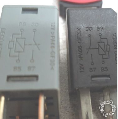
Ween, on these relays pin 85 is diagonal from pin 30. So I went with that instead of 87 since 87 is the gate(?)
Results of 85 to 85 jumper. With the defrost switch (off) the compressor runs constant. Defrost switch (on) the compressor cycles indicating that the compressor relay is operating solo.
Im having trouble with the logic unless it's a polarity thing with pins 85/86.
Relay, 2010 Chevy Pickup AC - Last Post -- posted image.
tpntx 
Member - Posts: 6
Member spacespace
Joined: July 24, 2017
Location: Texas, United States
Posted: July 25, 2017 at 10:32 AM / IP Logged Link to Post Post Reply Quote tpntx
Or could it be the compressor (black one) is normally closed?
Ween 
Platinum - Posts: 1,366
Platinum spacespace
Joined: August 01, 2004
Location: Illinois, United States
Posted: July 25, 2017 at 12:38 PM / IP Logged Link to Post Post Reply Quote Ween
Do you have a multimeter? Place meter on ohms. Probe relay terminals. Two terminals should have around 80 ohms of resistance between them...these are the coil. The other two are the contacts. They should be diagonal sets, this way it doesn't matter how the relay is orientated in the fuse box.
Ween 
Platinum - Posts: 1,366
Platinum spacespace
Joined: August 01, 2004
Location: Illinois, United States
Posted: July 25, 2017 at 12:39 PM / IP Logged Link to Post Post Reply Quote Ween
Post a better pic of the relays, or inspect and see if terminal numbers are on the base...by the terminals.
tpntx 
Member - Posts: 6
Member spacespace
Joined: July 24, 2017
Location: Texas, United States
Posted: July 25, 2017 at 12:44 PM / IP Logged Link to Post Post Reply Quote tpntx
Yep they where on the base. Works like it should. Thanks again I really appreciate your help.

If you wish to post a reply to this topic, you must first login.
If you are not already registered, you must first register.

  Printable version Printable version Post ReplyPost New Topic
You cannot post new topics in this forum
You cannot reply to topics in this forum
You cannot delete your posts in this forum
You cannot edit your posts in this forum
You cannot create polls in this forum
You cannot vote in polls in this forum

  •  
Search the12volt.com
Follow the12volt.com Follow the12volt.com on Facebook
Friday, April 26, 2024 • Copyright © 1999-2024 the12volt.com, All Rights Reserved Privacy Policy & Use of Cookies
Disclaimer: *All information on this site ( the12volt.com ) is provided "as is" without any warranty of any kind, either expressed or implied, including but not limited to fitness for a particular use. Any user assumes the entire risk as to the accuracy and use of this information. Please verify all wire colors and diagrams before applying any information.

Secured by Sectigo
the12volt.com spacer
Support the12volt.com
Top
the12volt.com spacer