the12volt.com spacer
icon

Astrostart Module Replacement Programing


Post ReplyPost New Topic
< Prev Topic Next Topic >
lemoncadillac 
Member - Posts: 12
Member spacespace
Joined: February 10, 2018
Location: Minnesota, United States
Posted: February 28, 2018 at 5:18 PM / IP Logged  
Astrostart Module Replacement Programing - Page 2 -- posted image. Astrostart Module Replacement Programing - Page 2 -- posted image. Astrostart Module Replacement Programing - Page 2 -- posted image. Astrostart Module Replacement Programing - Page 2 -- posted image. Astrostart Module Replacement Programing - Page 2 -- posted image. Astrostart Module Replacement Programing - Page 2 -- posted image.
lemoncadillac 
Member - Posts: 12
Member spacespace
Joined: February 10, 2018
Location: Minnesota, United States
Posted: February 28, 2018 at 5:30 PM / IP Logged  
Please look at P5. I may not have switched these wires correctly.
P5: PROGRAMMABLE RELAY
This is a three-pin connector connected to an internal standard automotive style relay, i.e. COMMON-30, N.O.
(normally open)-87 and N.C. (normally closed)-87A.This connector is there to save an external relay in your
installation. The installation of this relay requires a maximum of 3 wires. Refer to Stage 1 - Level 9 on page 20 for
more details about the options available on this output.
Cut to White wire supplied in the box for the wiring of this output.
monty_77 
Copper - Posts: 491
Copper spaceThis member has made a donation to the12volt.com. Click here for more info.spacespace
Joined: January 15, 2009
Location: North Dakota, United States
Posted: February 28, 2018 at 6:46 PM / IP Logged  
The picture did not show will look on my computer in a bit or I sent you my email pm and you gcould email them to me
lemoncadillac 
Member - Posts: 12
Member spacespace
Joined: February 10, 2018
Location: Minnesota, United States
Posted: February 28, 2018 at 6:56 PM / IP Logged  
Install Images
Astrostart Module Replacement Programing - Page 2 -- posted image.
monty_77 
Copper - Posts: 491
Copper spaceThis member has made a donation to the12volt.com. Click here for more info.spacespace
Joined: January 15, 2009
Location: North Dakota, United States
Posted: February 28, 2018 at 11:37 PM / IP Logged  
Wires on programmable relay look go, I usually put the constant 12volt to pin 87 and output to 30 common, so your pin 87a is not hot when not running, doesn’t matter ether way will still work the same,
What I was looking for was off the remote start on P2 harness where the white/blue, brown, white, and violet outputs where hooked to you vehicle? And the color wire it is attached to. Theses are four programmable outputs
I will all so need to know what color the white white in P5 is hooked to in vehicle as in color of wire on vehicle
If I had to just guess at programming for you this is what it would be with out knowing what the programmable outputs are hooked to
Do this with engine not running, key not in ignition, I will give you a set of dip switches that need to be on and after setting them you will push on brake and led should flash the number for the level to confirm programming and then move to the next one and so on.
Please note that I did not include setting for alarm features in this they can be changed later lets just get it to start first
Level 2
Dip switch 1 and 6 on all others off, push brake led on brain should flash 2 times
Please note that I do not know what the programmable outputs are doing so I will not have you change level 5,6,7,or 8 with out more information
Level 9
Dip switches 1,4,7,8 on all others off and push brake led should flash 9 times
Level 12
Dip switches 3,4,8 on all others off push brake led should flash 12 times, this will give you the longest runtime
Move all dip switches to off and hit brake one more time
You can try to remote start make sure shut off switch is on
This is the best I can do with out knowing what starter wires are attached to what color wires on the vehicle, if I get the right ones we can talk about a alarm setting too,
Example starter wire p4 dark blue is connected to vehicle wire yellow, I can figure it out from there
lemoncadillac 
Member - Posts: 12
Member spacespace
Joined: February 10, 2018
Location: Minnesota, United States
Posted: February 28, 2018 at 11:57 PM / IP Logged  
You are my hero!!!! It started and is running now.
lemoncadillac 
Member - Posts: 12
Member spacespace
Joined: February 10, 2018
Location: Minnesota, United States
Posted: March 01, 2018 at 12:30 AM / IP Logged  
starter wire p4 dark blue is connected to vehicle wire yellow,confirmed YES
lemoncadillac 
Member - Posts: 12
Member spacespace
Joined: February 10, 2018
Location: Minnesota, United States
Posted: March 01, 2018 at 4:45 PM / IP Logged  
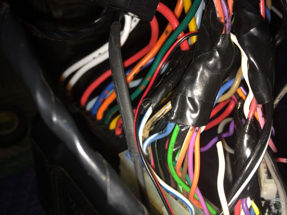
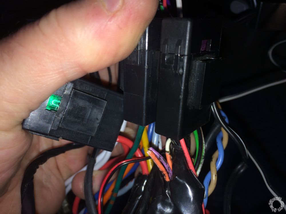
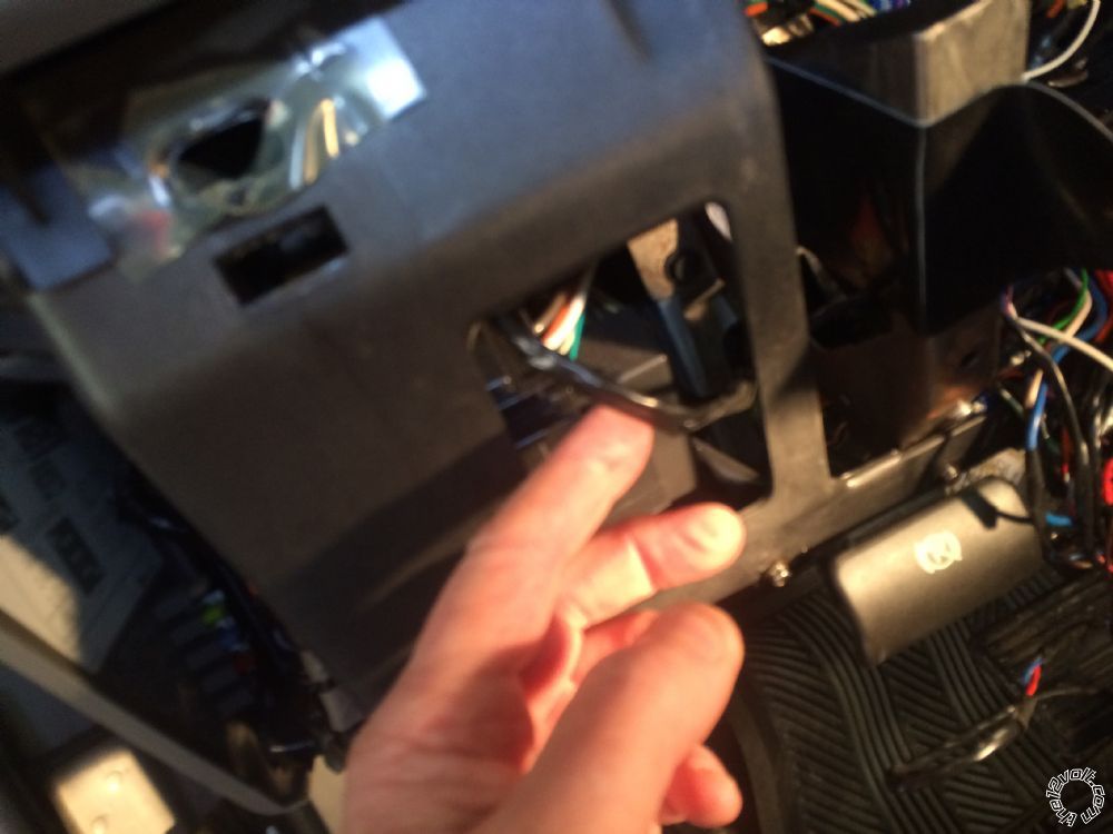
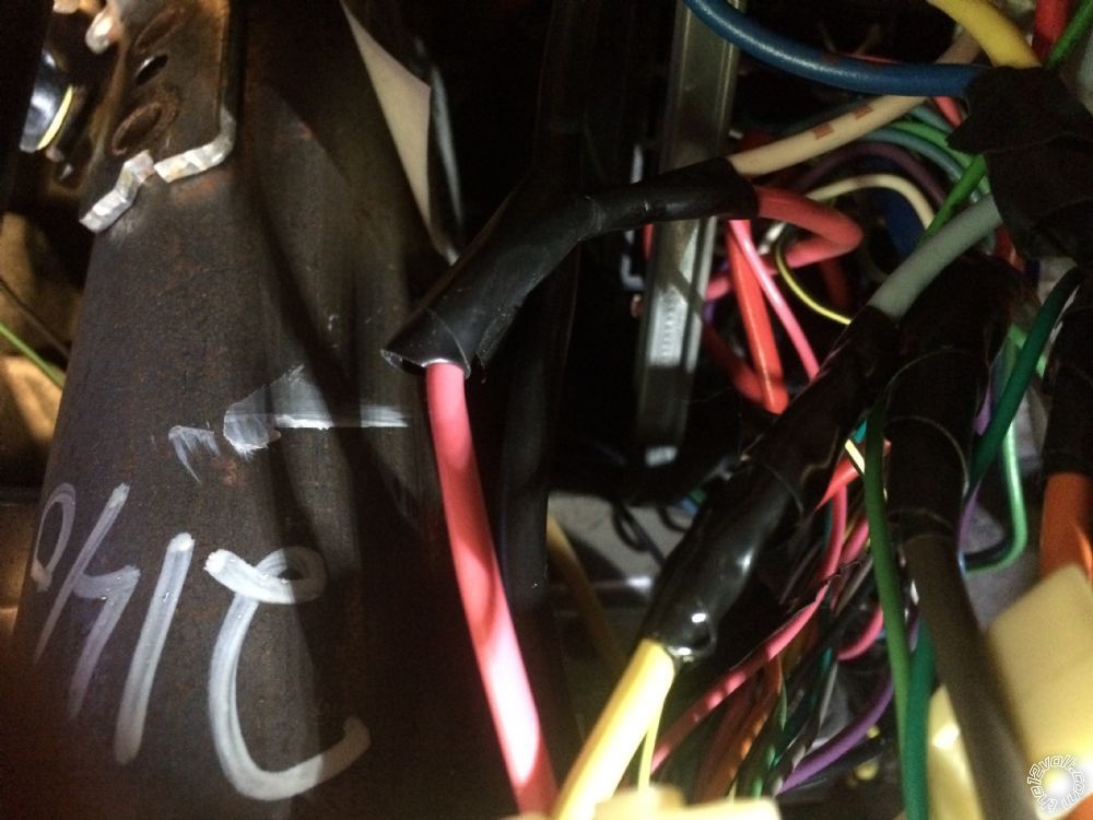
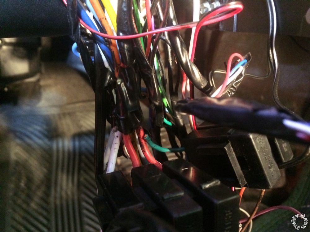
P2 white/blue. Go up in the dash. See pic. Others cut see pics.
P5. 1 white ties into pink
Other white fused and then ties into red
I will attach pics once I am back in the house
lemoncadillac 
Member - Posts: 12
Member spacespace
Joined: February 10, 2018
Location: Minnesota, United States
Posted: March 01, 2018 at 5:28 PM / IP Logged  
Astrostart Module Replacement Programing - Page 2 -- posted image.Astrostart Module Replacement Programing - Page 2 -- posted image.Astrostart Module Replacement Programing - Page 2 -- posted image.Astrostart Module Replacement Programing - Page 2 -- posted image.Astrostart Module Replacement Programing - Page 2 -- posted image.
Page of 2

Sorry, you can NOT post a reply.
This topic is closed.

  Printable version Printable version Post ReplyPost New Topic
You cannot post new topics in this forum
You cannot reply to topics in this forum
You cannot delete your posts in this forum
You cannot edit your posts in this forum
You cannot create polls in this forum
You cannot vote in polls in this forum

  •  
Search the12volt.com
Follow the12volt.com Follow the12volt.com on Facebook
Tuesday, April 30, 2024 • Copyright © 1999-2024 the12volt.com, All Rights Reserved Privacy Policy & Use of Cookies
Disclaimer: *All information on this site ( the12volt.com ) is provided "as is" without any warranty of any kind, either expressed or implied, including but not limited to fitness for a particular use. Any user assumes the entire risk as to the accuracy and use of this information. Please verify all wire colors and diagrams before applying any information.

Secured by Sectigo
the12volt.com spacer
Support the12volt.com
Top
the12volt.com spacer