the12volt.com spacer
icon

Keyless entry on a 93 Ford Tempo


Post ReplyPost New Topic
< Prev Topic Next Topic >
snes_83 
Member - Posts: 15
Member spacespace
Joined: July 30, 2002
Location: United States
Posted: July 31, 2002 at 8:58 PM / IP Logged  

Hi, could someone please help me with my 93 Ford Tempo keyless entry installation?

I am having trouble getting the lock / unlock to work with my Omega REC-11 keyless entry. I also have 4 bosch relays available.

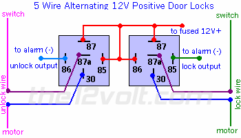
I think that I have "5 Wire Alternating (+) 12 V DC"  I'm pretty sure that the pink/green wire is lock, and the pink / YELLOW wire is unlock.

This is how I currently have it wired:

Keyless entry on a 93 Ford Tempo -- posted image.

On each switch, 1 wire is constant 12 V, one is the unlock wire, the other is the lock wire, and 2 are ground wires.

I have tried hooking it up many ways, but the relays just make clicking noises, and nothing happens. PLEASE PLEASE PLEASE help!!  I have already spent a whole weekend trying to get this working.  ****Whoever helps me the most to get this work, I will give $20.00 using PayPal.**** (no lie)

-Tom

Velocity Motors 
Moderator - Posts: 12,488
Moderator spaceThis member has made a donation to the12volt.com. Click here for more info.spaceThis member has been recognized as an authority in Electrical Theory. Click here for more info.spaceThis member has been recognized as an authority in Fabrication. Click here for more info.spaceThis member has been recognized as an authority in Mobile Audio and Video. Click here for more info.spaceThis member has been recognized as an authority in Mobile Security and Convenience. Click here for more info.spacespace
Joined: March 08, 2002
Location: Manitoba, Canada
Posted: August 01, 2002 at 1:06 AM / IP Logged  

Your car has a (+) type door lck system. If your alarm has alternatinf polarity door lock wires, then hook straight up to the alarm otherwise you will need this diagram to hook up the door locks to reverse the (-) signal from the alarm: https://www.the12volt.com/doorlocks/page3.asp#3wp

Jeff
Velocity Custom Home Theater
Mobile Audio/Video Specialist
Morden, Manitoba CANADA
snes_83 
Member - Posts: 15
Member spacespace
Joined: July 30, 2002
Location: United States
Posted: August 02, 2002 at 11:40 AM / IP Logged  

Ok, I couldn't get it to work with the information that you gave me.

Here are some more details about my installation:

On each door switch, I have 5 wires.  The pink/green wire rests at ground and shows 12 V positive when I hit the lock buttton.  The pink / YELLOW wire rests at ground and shows 12 V positive when I hit the unlock button. There are also 2 ground wires and 1 constant 12 V wire on each switch.

My keyless entry system has negitive lock and negative unlock outputs.

When I tried hooking it up using the diagram you gave me, I got a high pitched squealy noise from the relays, and it didn't work. When I tried hooking it up straight to the keyless entry system, it did nothing.

I have also tried hooking it up as "5 wire alternating 12V positive door locks" with no luck. (maybe I'm hooking it up wrong???)

One more question.... What is "the optional DLS"??  In my manual, it recommends that I use this, and it also says that "some doorlock systems, however, require more than the 500ma ground output that the keyless entry system's control module can accomodate". So do I need to get one of these or not?  I don't know what this "DLS" thing really does...

Whover replys next, could you give me some extra details?? This is my first time installing one of these, and this message board and my instruction manual assume that I know what I'm doing (and I don't)

That $20.00 offer on PayPal still stands if anyone can help me get this working.....

snes_83 
Member - Posts: 15
Member spacespace
Joined: July 30, 2002
Location: United States
Posted: August 02, 2002 at 1:35 PM / IP Logged  

PLEEEEEEEEASE HELP

I don't want to return this thing to crutchfield

joyride2k 
Member - Posts: 40
Member spacespace
Joined: August 02, 2002
Location: United States
Posted: August 02, 2002 at 7:05 PM / IP Logged  
First thing you need to do is make sure your outputs from your RKE module still work, they may have been fried. To do this take you DMM or test light and clip your positive lead to 12V+ and clip the other lead to your lock or unlock wire on your RKE module. Now use the remote and trigger the lock or unlock. If your module is still good, your DMM will flash 12V+, or your test light will flash.
After that, find your target wires (pink / YELLOW, pink/green) and cut the wire. If you have the right wire, when you hit the button on the door it won't function. Now you have to find which is your motor side and which is your switch side of the wire you just cut in half. Take your DMM or test light and clip one lead to ground and the other lead to the side of the wire you are testing. For the pink / YELLOW, when you hit the lock button on the door, if you have the SWITCH side the DMM will show 12V+, or your test light will flash. If you have the MOTOR side of the wire nothing will happen. When you have figured out which is the motor side and which is the switch side label it or just remember. *A quick test to find the MOTOR side of the wire is to supply it with 12V+, if you have the MOTOR side the door lock/unlock function will work.
Do the same procedure on the pink/green unlock wire as well.
Now get your relays wired up as follows:
lock relay:
85 -> Green on RKE module
86 -> 12V+
87 -> 12V+
87a -> pink / YELLOW SWITCH side of vehicle
30-> pink / YELLOW MOTOR side of vehicle
unlock relay:
85 -> Blue on RKE module
86 -> 12V+
87 -> 12V+
87a -> pink/green SWITCH side of vehicle
30 -> pink/green MOTOR side of vehicle
*Remember that when you cut the lock/unlock wire in the vehicle, that function no longer worked when you hit the button on the door. If you have the relay wired up correctly and connected to you lock/unlock wires, when you hit the switch on the door that function should now work again, if not check to make sure your relay's are wired correctly.
Now try your RKE, it should work, if not you may have the SWITCH and MOTOR side backwards.
I tried to go through this step by step, I hope it helps.
snes_83 
Member - Posts: 15
Member spacespace
Joined: July 30, 2002
Location: United States
Posted: August 03, 2002 at 12:34 AM / IP Logged  

Thanks a lot,

I have done what you have said EXACT once before, so it IS possible that i have fried something...

THANKS A LOT....If I get this to work on saturday night, I'll owe you 20 bucks. (I appreciate the extra details)

Its 1:35 AM here right now, and i'm kinda tired...

Keyless entry on a 93 Ford Tempo -- posted image.

- Tom

snes_83 
Member - Posts: 15
Member spacespace
Joined: July 30, 2002
Location: United States
Posted: August 03, 2002 at 11:56 PM / IP Logged  

Ok, i tested the positive / negative outputs on the RKE module, and they are between .5 and 1 volts......I think it's fried....(the lock / unlock wires from the RKE should both be 12 volts..right??)

If it is fried, i'll just buy another one....they aren't TOO expensive....

Keyless entry on a 93 Ford Tempo -- posted image.

joyride2k 
Member - Posts: 40
Member spacespace
Joined: August 02, 2002
Location: United States
Posted: August 04, 2002 at 7:00 AM / IP Logged  
I'm not sure on how many volts they put out? Is it enough to energize the coil in the relay?
Quick test to find out would be:
85 -> lead from RKE
86 -> 12V+
87 -> positive lead of DMM/test light
87a -> not used
30 -> 12V+
then connect your negative DMM/test light lead to ground. Use your RKE, if it's still good it will switch the relay and you'll get a reading on your DMM.
snes_83 
Member - Posts: 15
Member spacespace
Joined: July 30, 2002
Location: United States
Posted: August 05, 2002 at 6:26 PM / IP Logged  

I've got another question.............

Uhm, I'm not so sure that I've got "5 wire alternating 12V positive door locks" because when I supply 12 V to the motor side of the cut wire, NOTHING HAPPENS!!!!

What does it take for me to activate the lock manually?? (without pressing the button on the switch) Remember: I have 1 lock wire, 1 unlock wire, 1 constant 12 V, and 2 ground wires on each lock switch.

The relays made a high pitched, squealy noise when I pressed the lock / unlock button on the remote (so it was obviously the wrong way to hook it up).

ALSO, I HAVE BURNED OUT THE DRIVER'S SIDE DOOR LOCK SWITCH BY WIRING IT AS "5 wire alternating 12V positive door locks", AND I HAVE ANOTHER SWITCH BEING SENT TO ME SPECIAL ORDER BY ADVANCE AUTO PARTS.

I have tested all of my equipment (RKE, and 4 relays) and they all still work (nothing is fried) , I'm just not wiring it correctly.

Please, someone help me figure this thing out!!!! (IT IS DRIVING ME CRAZY)

Keyless entry on a 93 Ford Tempo -- posted image.

Velocity Motors 
Moderator - Posts: 12,488
Moderator spaceThis member has made a donation to the12volt.com. Click here for more info.spaceThis member has been recognized as an authority in Electrical Theory. Click here for more info.spaceThis member has been recognized as an authority in Fabrication. Click here for more info.spaceThis member has been recognized as an authority in Mobile Audio and Video. Click here for more info.spaceThis member has been recognized as an authority in Mobile Security and Convenience. Click here for more info.spacespace
Joined: March 08, 2002
Location: Manitoba, Canada
Posted: August 05, 2002 at 9:05 PM / IP Logged  

OK... where are you grabbing the wires from ?? In the door switch between the motor nd the switch or between the switch and the relay ?

Jeff
Velocity Custom Home Theater
Mobile Audio/Video Specialist
Morden, Manitoba CANADA
Page of 2

  Printable version Printable version Post ReplyPost New Topic
You cannot post new topics in this forum
You cannot reply to topics in this forum
You cannot delete your posts in this forum
You cannot edit your posts in this forum
You cannot create polls in this forum
You cannot vote in polls in this forum

  •  
Search the12volt.com
Follow the12volt.com Follow the12volt.com on Facebook
Sunday, May 19, 2024 • Copyright © 1999-2024 the12volt.com, All Rights Reserved Privacy Policy & Use of Cookies
Disclaimer: *All information on this site ( the12volt.com ) is provided "as is" without any warranty of any kind, either expressed or implied, including but not limited to fitness for a particular use. Any user assumes the entire risk as to the accuracy and use of this information. Please verify all wire colors and diagrams before applying any information.

Secured by Sectigo
the12volt.com spacer
Support the12volt.com
Top
the12volt.com spacer