the12volt.com spacer
icon

help with relays


Post ReplyPost New Topic
< Prev Topic Next Topic >
spear 
Member - Posts: 6
Member spacespace
Joined: October 10, 2004
Location: United States
Posted: November 19, 2004 at 9:04 PM / IP Logged  

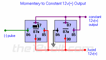
help with relays -- posted image.

I have been working (unsuccessfully) with the above setup, using the unlock pulse from my remote to turn on the courtesy and backup lights in my Tacoma.  I added a third relay to break contact between 85 and 87 using the door trigger to open the 87a-30 contacts.  That way  the lights come on with the unlock pulse and then go off when the door is opened (except courtesy lights stay on until door is shut).  Here are my questions.

#1 I had to add a fourth relay to convert the positive output to negative output.

Is there a way to do 'momentary to constant negative output' with fewer relays?

Also, when I add the 4th relay, I get problems with the latching not working.  I need diodes added I'm sure but don't know where. 

Could someone illustrate where the diodes go and maybe set up a diagram as I've tried to create?  THANK YOU!!!  :)

D'Ecosse 
Copper - Posts: 49
Copper spacespace
Joined: October 24, 2004
Posted: November 27, 2004 at 4:11 PM / IP Logged  

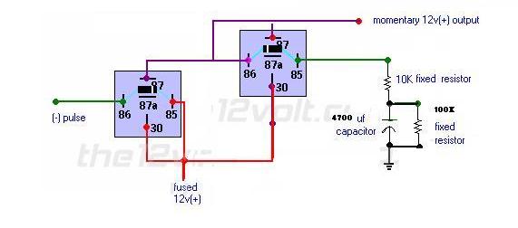
How about this?

This is a timer that will be triggered by your unlock pulse - should be good for ~ 30s or so (not sure exactly what voltage the relay will drop out at!) You can play with the R/C values a little to increase/decrease the time.

You'll still have to invert with another relay to get the -ve drive unfortunately, but you won'y have to worry about resetting - the 100K will discharge the cap.

help with relays -- posted image.

hotwaterwizard 
Silver - Posts: 1,350
Silver spacespace
Joined: December 11, 2003
Location: California, United States
Posted: November 27, 2004 at 11:42 PM / IP Logged  

Has this timer circuit been tested?

It looks like the resistors and Capacitor will cause a voltage drop and the coil will not pull in the relay.

It is a Passive Timing circuit and there will be a voltage loss.

John DeRosa (Hotwaterwizard)
Stockton California
When in doubt, try it out !
D'Ecosse 
Copper - Posts: 49
Copper spacespace
Joined: October 24, 2004
Posted: November 28, 2004 at 2:07 AM / IP Logged  

The capacitor when discharged will keep the resistors from being a typical votage divider until the cap charges up via the RC time constant, when then it will turn off. That's the whole point, that the relay will turn off when the cap charges sufficiently to create insufficient voltage acorss the coil to keep the relay energized

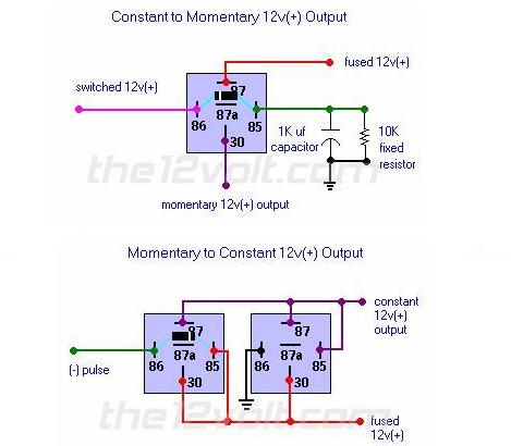
It's just a combination of these two relay circuits from the Relay: Special Application notes in the menu on the left, with some changes to the timing compnents:

https://www.the12volt.com/relays/page5.asp

.

help with relays -- posted image.

hotwaterwizard 
Silver - Posts: 1,350
Silver spacespace
Joined: December 11, 2003
Location: California, United States
Posted: November 28, 2004 at 2:31 AM / IP Logged  

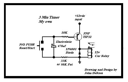
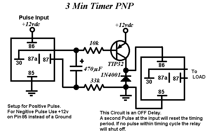
I guess I need to hook this up and see if it actually works. Here is a circuit that has ben tested and works well. A smaller Capacitor will change the Timing.

help with relays -- posted image.

John DeRosa (Hotwaterwizard)
Stockton California
When in doubt, try it out !
hotwaterwizard 
Silver - Posts: 1,350
Silver spacespace
Joined: December 11, 2003
Location: California, United States
Posted: November 28, 2004 at 3:02 AM / IP Logged  

Here is how I would do it.

help with relays -- posted image.

John DeRosa (Hotwaterwizard)
Stockton California
When in doubt, try it out !
hotwaterwizard 
Silver - Posts: 1,350
Silver spacespace
Joined: December 11, 2003
Location: California, United States
Posted: December 03, 2004 at 12:41 AM / IP Logged  

help with relays -- posted image.

I tried this circuit and it DOES NOT WORK

John DeRosa (Hotwaterwizard)
Stockton California
When in doubt, try it out !

Sorry, you can NOT post a reply.
This topic is closed.

  Printable version Printable version Post ReplyPost New Topic
You cannot post new topics in this forum
You cannot reply to topics in this forum
You cannot delete your posts in this forum
You cannot edit your posts in this forum
You cannot create polls in this forum
You cannot vote in polls in this forum

  •  
Search the12volt.com
Follow the12volt.com Follow the12volt.com on Facebook
Sunday, May 19, 2024 • Copyright © 1999-2024 the12volt.com, All Rights Reserved Privacy Policy & Use of Cookies
Disclaimer: *All information on this site ( the12volt.com ) is provided "as is" without any warranty of any kind, either expressed or implied, including but not limited to fitness for a particular use. Any user assumes the entire risk as to the accuracy and use of this information. Please verify all wire colors and diagrams before applying any information.

Secured by Sectigo
the12volt.com spacer
Support the12volt.com
Top
the12volt.com spacer