the12volt.com spacer
icon

U guys have come highly recommended


Post ReplyPost New Topic
< Prev Topic Next Topic >
kingpin111 
Member - Posts: 38
Member spacespace
Joined: February 10, 2005
Location: Canada
Posted: February 11, 2005 at 3:36 PM / IP Logged  

wheeeeeewww    heeeeeewwwwwwww!!!!!!!!!!!

i should of came here in the first place.  thanks to everybody. 

and thank you "FORBIDDEN"

just one more thing.  here is my equipment list.

1" MDF

liquid nails and 2 1/2 inch flat head wood screws(pre drilling the holes)for assembly

1/4 weatherstripping foam when attaching the speakers

latex caulking to seal the joints inside the box

jbl says no insulation

and drilling a small hole in the back of the box to pass the wires through, which i will fill with caulking.

any tips or comments

kingpin

stevdart 
Platinum - Posts: 5,816
Platinum spaceThis member has made a donation to the12volt.com. Click here for more info.spaceThis member has been recognized as an authority in Mobile Audio and Video. Click here for more info.spaceThis member consistently provides reliable informationspace
Joined: January 24, 2004
Location: Pennsylvania, United States
Posted: February 12, 2005 at 4:39 AM / IP Logged  

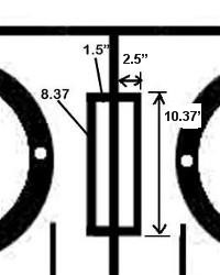
The port displacement is almost double what is spec'd in the manual because of the 1" MDF walls of the ports .  The JBL manual calculates the overall displacement of a standard thin-walled tube port and figures that into the box volume.  So, the difference is about +.09 cu ft displacement for each port.   Edge your internal volume in each chamber up slightly by about 160 in^3 to compensate.  The manual wants 2.25 ft^3 gross volume....you should go to 2.34 ft^3 to maintain the 30 Hz tuning frequency.

To figure it yourself :

U guys have come highly recommended - Page 3 -- posted image.

The displacement of your port assembly will be determined by where you actually place the ports in the box.  By your diagram the ports occupy center stage, so there will be a 1" sidewall added to 3 sides.  If the ports were moved to the bottom, the displacement would change (2 sidewalls added).  Model your finished design and figure the displacement including the port walls (but not including the middle baffle common wall).  Compare that displacement volume to 0.107 ft^3, which is, by my estimation, the displacement of a 4" X 13 5/16"  tube port.  Whatever you get as the difference, add that volume to the internal volume of each chamber.

Use https://www.the12volt.com/caraudio/boxcalcs.asp#cyl and https://www.the12volt.com/caraudio/boxcalcs.asp#rec for help.  Note:  You can always use '0' as the value in "thickness" when you are calculating volumes.  That way, the calculator uses only your 2 inputted measurements to figure volume and doesn't add for sides.

And remember:  After you make the compensation for port displacement, you will be at gross volume JBL recommendation, as they included only the driver and round port.   Anything you add to the interior volume above and beyond, such as corner blocks or braces, must be measured and the displacement added to the volume.

kingpin111 
Member - Posts: 38
Member spacespace
Joined: February 10, 2005
Location: Canada
Posted: February 12, 2005 at 7:48 PM / IP Logged  

and here i thought i was finished.

o.k.   so this is what i got.  the initial box volume is 2.25 cubic feet. here are the new measurements.

2.5 x 1 x 13.3(top and bottom sides of port)=33.25 x 2(top and bottom)=66.5cu.inches.

10.37 x 1 x 13.3(side of port)=137.92cu.inches

137.92(side) + 66.5(2 port sides) = 204.42cubic inches

204.42cu.inches/converted to cu.feet/ = .12cu.feet

.12cu.feet - .107cu.feet = .01

so i should add   .1cu.feet to the space.  is this right, it sounds wrong(self doubt).

can you please check if my math is correct.

thanks

kingpin

kingpin111 
Member - Posts: 38
Member spacespace
Joined: February 10, 2005
Location: Canada
Posted: February 12, 2005 at 7:52 PM / IP Logged  

that should be

.12cu.feet - .107cu.feet = .01

so i should add .01 cu.feet to the spaceU guys have come highly recommended - Page 3 -- posted image.

stevdart 
Platinum - Posts: 5,816
Platinum spaceThis member has made a donation to the12volt.com. Click here for more info.spaceThis member has been recognized as an authority in Mobile Audio and Video. Click here for more info.spaceThis member consistently provides reliable informationspace
Joined: January 24, 2004
Location: Pennsylvania, United States
Posted: February 12, 2005 at 9:22 PM / IP Logged  

You measured and figured the displacement of the MDF that surrounds the port.  It is better to measure the whole port structure (including air space) and compare it to what was allowed in the manual specs.  (Keep in mind the round plastic port has some volume in thickness of material, too.)  You didn't figure for the actual port opening in the above post, but you deducted what the specs allowed anyway.  You started with one approach, finished with another.  Result:  wrong answer.

When you do your math to figure cubic, see the object in 3 dimensions.  The port assembly is a box.  It consists of both the walls and the air space of the port.  Remember what Rob said in the beginning:

l * w * h = ft^3

12" * 12" *12" = 1728in^3

1728in^3 = 1ft^3

So if you look at one of the port "boxes", you see an object that measures in 3 dimensions.  The measurements are 2.5 x 10.37 x 13.31 = ?

Answer is 345 cu. inches.  Convert to cu. ft.:  345 / 1728 = 0.199 ft^3

The JBL specs already allow for .107 ft^3. (remember, we're allowing for some thickness of the plastic walls, too).   The new larger displacement is .199 ft^3

.199 minus .107 = .09 which is a hair away from one tenth of a cubic foot.  So as I said in the post above:

So, the difference is about +.09 cu ft displacement for each port.   Edge your internal volume in each chamber up slightly by about 160 in^3 to compensate.  The manual wants 2.25 ft^3 gross volume....you should go to 2.34 ft^3 to maintain the 30 Hz tuning frequency.

You have to add that one-tenth of a cubic foot to each of the two chambers.  If it were a lot less than that you wouldn't be worrying about it.  But .09 ft^3 is 160 in^3...when you look at it like that you can better see how much space that is.  It's enough to throw off the tuning frequency, not by much but I'm thinking you want to be able to knowingly say your box is tuned to 30 Hz.  Am I right?  You have the links to the calculators and read again the notes I made about using them.  You've got the basics that you need to get the volume right. 

And one other thing....I would not build a box that is that deep without adding an internal brace.  I advise using the bracing I described earlier (it's easily cut out of a single piece of MDF).  And as said earlier, the bracing displaces volume, too, so you have to compensate for it.  Placing it to brace front-to-back is best, but if room is lacking side-to-side is what you want to do.

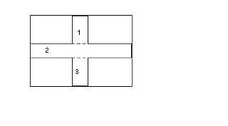
A brace might look like this:

U guys have come highly recommended - Page 3 -- posted image.

After you cut it out, you would measure it by, again, looking at it as a 3-dimensional object.  To do this, you would divide it up into manageable sections like I've numbered in the pic.  1" would be the common depth (for the MDF thickness).  Add them up and you've got the displacement that you have to add to the overall volume.

A lot of people just say hell with it, it's good enough.  But the best enclosures come from those who are precise with their measurements.  And it's especially important when dealing with a vented enclosure. 

kingpin111 
Member - Posts: 38
Member spacespace
Joined: February 10, 2005
Location: Canada
Posted: February 12, 2005 at 10:17 PM / IP Logged  

alright, i got what you are saying now.  i was a little confused at your earlier post. after reading it over a couple times and reading your latest post i understand things better.

i took your measurements of 2.34cu.feet and added another .03cu.ft(brace) = 2.37cu.feet.

17.25 wide  x  16 high  x  21.25 deep = 2.378cu.feet.

thanks

kingpin

stevdart 
Platinum - Posts: 5,816
Platinum spaceThis member has made a donation to the12volt.com. Click here for more info.spaceThis member has been recognized as an authority in Mobile Audio and Video. Click here for more info.spaceThis member consistently provides reliable informationspace
Joined: January 24, 2004
Location: Pennsylvania, United States
Posted: February 12, 2005 at 10:35 PM / IP Logged  

Good job.  But by the displacement you posted for a brace, I would guess that they might be a little too narrow for the strength you want.  I would go about 3" width, maybe up to 4".  I'm thinking you should have .05 to .06 ft^3 per brace.   (And I'll take your word for it on those dimensions.  You know what the max OD can be.)

kingpin111 
Member - Posts: 38
Member spacespace
Joined: February 10, 2005
Location: Canada
Posted: February 12, 2005 at 11:05 PM / IP Logged  

on the volume calculator:

15.25  x  14  x  19.25  inside dimensions(0.0 material thickness) = 2.3784cu.feet

17.25  x  16  x 21.25 outside dimensions(1.0) material thickness)=2.3784cu.feet

"And, I just caught this:  you are figuring internal dimensions now for volume.  You won't be able to go 16" H on the inside.  Nor can you go that width.  You'll have 2" total for height to add for OD and 3" total in width.  You'll have to push it to the rear."U guys have come highly recommended - Page 3 -- posted image.

you have totally lost me with this.

i appreciate you sticking with this thread and helping me.  as i like to do things properly.  i can say with all honestly that you guys have earned my respect as this is not as easy as it looks to get it done properly.

sorry if i am trying your patience, i just dont want to do things half assed. 

i am feeling pretty stupid about now.

kingpin

kingpin111 
Member - Posts: 38
Member spacespace
Joined: February 10, 2005
Location: Canada
Posted: February 12, 2005 at 11:09 PM / IP Logged  

hey STEVDART

did you just edit your post.  am i missing something here.

kingpin

stevdart 
Platinum - Posts: 5,816
Platinum spaceThis member has made a donation to the12volt.com. Click here for more info.spaceThis member has been recognized as an authority in Mobile Audio and Video. Click here for more info.spaceThis member consistently provides reliable informationspace
Joined: January 24, 2004
Location: Pennsylvania, United States
Posted: February 12, 2005 at 11:22 PM / IP Logged  

Yeah, sorry.  At first I thought you posted inside measurements, then I checked with a calc.  Then I edited.  lol

U guys have come highly recommended - Page 3 -- posted image. STOP ME!  (You'll get a button some day.)

Page of 4

  Printable version Printable version Post ReplyPost New Topic
You cannot post new topics in this forum
You cannot reply to topics in this forum
You cannot delete your posts in this forum
You cannot edit your posts in this forum
You cannot create polls in this forum
You cannot vote in polls in this forum

  •  
Search the12volt.com
Follow the12volt.com Follow the12volt.com on Facebook
Monday, May 13, 2024 • Copyright © 1999-2024 the12volt.com, All Rights Reserved Privacy Policy & Use of Cookies
Disclaimer: *All information on this site ( the12volt.com ) is provided "as is" without any warranty of any kind, either expressed or implied, including but not limited to fitness for a particular use. Any user assumes the entire risk as to the accuracy and use of this information. Please verify all wire colors and diagrams before applying any information.

Secured by Sectigo
the12volt.com spacer
Support the12volt.com
Top
the12volt.com spacer