the12volt.com spacer
icon

Delayed relay output?


Post ReplyPost New Topic
< Prev Topic Next Topic >
icarus_icarus 
Copper - Posts: 229
Copper spacespace
Joined: November 01, 2005
Location: Ontario, Canada
Posted: November 11, 2005 at 1:54 AM / IP Logged  

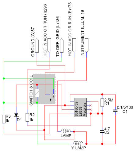
I finished a schematic of the switch Delayed relay output? - Page 6 -- posted image.

Delayed relay output? - Page 6 -- posted image.

icarus_icarus 
Copper - Posts: 229
Copper spacespace
Joined: November 01, 2005
Location: Ontario, Canada
Posted: November 11, 2005 at 2:03 AM / IP Logged  

Opps, the input (B) 175, should be 'HOT AT ALL TIMES'... sorry ;)

dualsport 
Silver - Posts: 983
Silver spacespace
Joined: September 27, 2005
Location: United States
Posted: November 11, 2005 at 2:25 AM / IP Logged  
Well, looks like you just have to supply a momentary pulse to the green node to latch the relay on. The coil is connected directly to the defrost grid without diode isolation, so do you need the heavy duty relay, connected as fingazz mentioned. Don't connect anything to the red side of the coil, or thar she blows..
Think the way it works is that the chip provides the ground for the red side of the coil when I-296 is powered in ACC or Run (Does your defroster really work when the key is in ACC position? I would have thought it should only be enabled when in Run)
Then when you push the relay contact closed, the green side of the relay coil gets 12V and latches on, until the timer decides it's had enough, and opens up the ground, releasing the relay and turning the defroster off again.
dualsport 
Silver - Posts: 983
Silver spacespace
Joined: September 27, 2005
Location: United States
Posted: November 11, 2005 at 2:28 AM / IP Logged  
Delayed relay output? - Page 6 -- posted image. Oops,that should have read, "so you *do* need the heavy duty relay...", not a question-
icarus_icarus 
Copper - Posts: 229
Copper spacespace
Joined: November 01, 2005
Location: Ontario, Canada
Posted: November 11, 2005 at 2:33 AM / IP Logged  

So it will latch the relay I'm adding? I don't quite follow what you mean by were I should hook up the new relay from the RS, sorry...

icarus_icarus 
Copper - Posts: 229
Copper spacespace
Joined: November 01, 2005
Location: Ontario, Canada
Posted: November 11, 2005 at 2:38 AM / IP Logged  

..I would hook the relay up 87 to one side of the switch itself, and 30 to the other side? So it would latch the relay I'm using and still use the timer in the circuit???

Correct me if I'm wrong plzs :)

dualsport 
Silver - Posts: 983
Silver spacespace
Joined: September 27, 2005
Location: United States
Posted: November 11, 2005 at 9:11 AM / IP Logged  
Your new relay doesn't need to latch, if you just momentarily close the connection between the existing relay, it should energize and latch that OEM relay. Then the timing is controlled by the OEM defrost timer, turning off when it releases the ground on the other side of the coil.
Connect your RS relay's 87 and 30 across the OEM relay contacts, (I)296 and (L)186 in your diagram.
You could splice in on the harness side if that's any easier than going to the relay directly. The way it looks, just applying 12v to the defroster grid from anywhere will do the same thing, while in run mode.
Again, before doing any splicing or wiring, I'd just make sure it works as expected when you provide the electrical connection without physically pushing the button and moving the OEM contact arm. See if the OEM relay pulls in and latches-
Did you test that yet?
icarus_icarus 
Copper - Posts: 229
Copper spacespace
Joined: November 01, 2005
Location: Ontario, Canada
Posted: November 11, 2005 at 11:12 PM / IP Logged  

I dunno where to hook up wires to test to see if it will latch itself or not (you said dont hook anything up to the red side, so I'm not sure what other spot will 'pull' it in, if it even will)... I don't want to fry the switch as parts for these cars are hard to find around here :( I don't think it will pull the switch closed as the spring onit is pretty stiff and would take a heck a lot to pull...

icarus_icarus 
Copper - Posts: 229
Copper spacespace
Joined: November 01, 2005
Location: Ontario, Canada
Posted: November 11, 2005 at 11:34 PM / IP Logged  

I also have problems with the remote starter unit itself :(

I needed to split the Acc output as it has only one wire and my car needs two. I hooked two relays to the acc wire (86 on each relay to the Acc wire from the RS, 85 on each to 'ground out while running') and then powered the wires seperately. (The manual says to diode isolate each relay at 'ground out while running' wire, so I put the diode stripes towards the RS module, right?) This is the way I did it first and nothing. Then tried reversing the diodes, nothing... So then I disconnected both relays and started it with the remote and checked the Acc wire from the RS, no power at all coming from it :( I tried to put the ground from the relays direct to the frame after this to see if the diodes were bad and still no go...

I think it has a dead relay in the RS unit as it is not outputting power at all the Acc cicuit. I even pulled the cover off the module and theres no power coming from the relay contact to the output terminal and the cover of just the Acc relay is warmer than the other relays in there and I din't feel it click when remote starting :( I will take it to the store and exchange it tomorrow...

My luck stinks when it comes to my car, lol... Hence why I am hesitant to fool with the defrost switch much ;)

dualsport 
Silver - Posts: 983
Silver spacespace
Joined: September 27, 2005
Location: United States
Posted: November 12, 2005 at 11:20 AM / IP Logged  

Sounds like you had it wired okay the first time with the diode stripe toward the RS ground while running. 

Did you have the ACC out from the RS hooked up directly to the car before splitting it using the relays?  Maybe the output rating of the RS output couldn't handle the draw of the circuit-  always safer to use the output to drive an external relay if you're not sure, so it protects the RS.

The connections to the defroster relay should be at the heavy solder connections, if you check continuity with your DMM when you push the switch closed (out of car, unpowered), you should see a connection between those two points.

Page of 11

  Printable version Printable version Post ReplyPost New Topic
You cannot post new topics in this forum
You cannot reply to topics in this forum
You cannot delete your posts in this forum
You cannot edit your posts in this forum
You cannot create polls in this forum
You cannot vote in polls in this forum

  •  
Search the12volt.com
Follow the12volt.com Follow the12volt.com on Facebook
Friday, May 17, 2024 • Copyright © 1999-2024 the12volt.com, All Rights Reserved Privacy Policy & Use of Cookies
Disclaimer: *All information on this site ( the12volt.com ) is provided "as is" without any warranty of any kind, either expressed or implied, including but not limited to fitness for a particular use. Any user assumes the entire risk as to the accuracy and use of this information. Please verify all wire colors and diagrams before applying any information.

Secured by Sectigo
the12volt.com spacer
Support the12volt.com
Top
the12volt.com spacer