the12volt.com spacer
icon

Integrating garage opener


Post ReplyPost New Topic
< Prev Topic Next Topic >
infinkc 
Copper - Posts: 438
Copper spacespace
Joined: October 28, 2002
Location: United States
Posted: February 22, 2006 at 2:30 PM / IP Logged  
ive always just left the remote in one piece in the dash with 2 wires coming out from the switch and going to a relay from the alarm to trigger the button press. The remote battery lasts about 2 years so when it gets low i just change it out, instead of the hastle of hardwiring it all in the car. I also dont run a momentary switch to the car, i just press the alarm remote to open the door. Main reason i did it is because i park my car outside sometimes and dont want someone to break into my car and take the remote (had it happen before to get access to the garage).
There are 10 types of people in the world, ones that understand binary and ones that dont.
D'Ecosse 
Copper - Posts: 49
Copper spacespace
Joined: October 24, 2004
Posted: February 22, 2006 at 6:53 PM / IP Logged  

You can make yourself a really compact (&cheap!) voltage converter/regulator with parts available from Radio Shack - you only need three components!

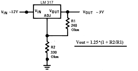
Get yourself an LM317T and connect two resistors up as shown in the image below - the values of the resistors will determine the output voltage based on the equation Vout = 1.25*(1+R2/R1)

Integrating garage opener - Page 2 -- posted image.

For this case, for Vout =3V (per your requirement), select resistors of 240 Ohm for R1 & 330 Ohm for R2

Using the equation Vout = 1.25* (1 + 330/240) = 1.25* (1+ 1.375) = 1.25*2.375 = 2.97V or ~3V

Here's a resistor calculator link to determine the values for those who are mathematically challenged! Integrating garage opener - Page 2 -- posted image.

You can eliminate the capacitors shown in the calculator schematic - they shouldn't be necessary since you're dealing a with a DC/DC conversion.

Actually it will be easier to find single preferred resistor values of 470 ohm & 680 ohm which gives 3.06V - you can also either use a potentiometer for variable or just make up the resistor value with two individual resistors (e.g. 240 = 120 + 120 which are more readily available as preferred values)  Resistors come in packs of 5 anyway at RadioShack so no extra cost involved, just another solder joint.

For those of you with 9V remotes incidentally simply use 1.5K for R2 (with R1 of 240 ohms) to give 9V out instead of 3V

Alpine DVA-7996; TME-760; SEAS Lotus Reference; Phase Linear Aliante 10Si Sub; Tru Technology C-7; Tru T2-100; D'Ecosse custom sub-box.
iceohio 
Member - Posts: 37
Member spacespace
Joined: November 26, 2005
Location: United States
Posted: February 22, 2006 at 6:54 PM / IP Logged  

They'd have a real hard time stealing my remote ;-)

It's up behind the instrument panel now.  That's why I really wanted to give it a power source, so I wouldn't need to ever worry about the batteries again.  Even though I've become quite an expert at getting it all off, I'd rather avoid it. 

I just ordered an automatic headlight kit.  I'm thinking that'll be the last electrocal tweak I'll do for the Jeep (beyond adding the radar and tilt sensors).  Those are prewired so no hardship.

I've batted around power windows.  They make kits for the Jeep making the buttons look very OEM, but I am even to the point of taking the Jeep emblem off of it for fear of embarassment.  I mentioned to a buddy who is a Jeep purist I added the door lock actuators and he went off the deep end.

But then again he won't recognize it as a Jeep anyway because it has an AT and AC.

heheh

Joseph

iceohio 
Member - Posts: 37
Member spacespace
Joined: November 26, 2005
Location: United States
Posted: February 22, 2006 at 7:12 PM / IP Logged  

Outstanding!

You just saved me about $15 and gave me a project :)

Thanks!

D'Ecosse 
Copper - Posts: 49
Copper spacespace
Joined: October 24, 2004
Posted: February 22, 2006 at 9:22 PM / IP Logged  

No problem - very simple little project that you'll feel good about making.

Probably find a dozen uses for these now! Integrating garage opener - Page 2 -- posted image.

You could consider making it on a small board ( like this one) - it should fit nicely in the std battery location.

Alpine DVA-7996; TME-760; SEAS Lotus Reference; Phase Linear Aliante 10Si Sub; Tru Technology C-7; Tru T2-100; D'Ecosse custom sub-box.
dualsport 
Silver - Posts: 983
Silver spacespace
Joined: September 27, 2005
Location: United States
Posted: February 22, 2006 at 11:39 PM / IP Logged  
You might try upping the resistance values a bit to reduce the amount of power the regulator circuit draws, since it'll be on all the time in this application.
It should still regulate properly with higher values, though there's a limit to how high you can go due to the adjustment pin current.
Just maintain the same ratio and it should work okay-
iceohio 
Member - Posts: 37
Member spacespace
Joined: November 26, 2005
Location: United States
Posted: February 22, 2006 at 11:52 PM / IP Logged  

Unfortunately I don't follow this.  If I increase the resistence, either the voltage or current will need to drop.  I don't want the voltage to drop much below 3V... But at the same time, I don't want a fire under the dash from a board melting either...

What values would you recommend for R1 & R2 above?

Basically, I'm just the yahoo at the end soldering it all together ;-)

Joseph

dualsport 
Silver - Posts: 983
Silver spacespace
Joined: September 27, 2005
Location: United States
Posted: February 23, 2006 at 12:25 AM / IP Logged  
You could try 4.7k and 3.9k for R2 and R1 respectively-
The output voltage is then 1.25(1+R2/R1) + Iadj(R2), with Iadj about 50uA.
With the smaller resistance values, the second term is negligible, but it becomes more significant with the larger value of R2, so it doesn't drop out.
Since there's some variation in regulators for the 50uA value, you can experiment with the values or use a pot like D'Ecosse mentioned to tweak it to the exact voltage you want. The voltage needed for the remotes aren't all that critical, since a new Li battery probably sits at 3.25V so, and the remote probabably still works okay at 2.8V.
D'Ecosse 
Copper - Posts: 49
Copper spacespace
Joined: October 24, 2004
Posted: February 23, 2006 at 12:47 AM / IP Logged  

From the application notes from the device manufacturer the recommended value for R1 is typically 240 ohms with R2 scaled appropriatley.

Your recommendation to select high resistance values not only goes against the design spec but also is completely unnecessary - you are talking about a total power dissipation of less than a 1/4W.

No need to make this complicated with confusion over excessive power drains thatfrankly aren't an issue.  

dualsport 
Silver - Posts: 983
Silver spacespace
Joined: September 27, 2005
Location: United States
Posted: February 23, 2006 at 2:33 AM / IP Logged  
1/4W may be normally considered negligible, but this is just adding to the power off current draw of the alarm and any other equipment using standby power.
Max recommended draw is 35mA, and having this in the power budget should be taken into consideration.
With 4mA constantly going through the resistors and the series pass regulator having to drop over 9V, it's going to be significant. Lot of wasted power with that much of a drop.
If the car is going to be driven regularly and not parked for any great lengths of time, then you can ignore the recommendations for key off power draw.
If it came down to needing that extra draw, I'd stick with the original battery power, especially since it's used only intermittently.
Page of 4

  Printable version Printable version Post ReplyPost New Topic
You cannot post new topics in this forum
You cannot reply to topics in this forum
You cannot delete your posts in this forum
You cannot edit your posts in this forum
You cannot create polls in this forum
You cannot vote in polls in this forum

  •  
Search the12volt.com
Follow the12volt.com Follow the12volt.com on Facebook
Wednesday, May 15, 2024 • Copyright © 1999-2024 the12volt.com, All Rights Reserved Privacy Policy & Use of Cookies
Disclaimer: *All information on this site ( the12volt.com ) is provided "as is" without any warranty of any kind, either expressed or implied, including but not limited to fitness for a particular use. Any user assumes the entire risk as to the accuracy and use of this information. Please verify all wire colors and diagrams before applying any information.

Secured by Sectigo
the12volt.com spacer
Support the12volt.com
Top
the12volt.com spacer