the12volt.com spacer
icon

Briding center channel speaker


Post ReplyPost New Topic
< Prev Topic Next Topic >
ShaunD912 
Copper - Posts: 140
Copper spacespace
Joined: July 09, 2002
Location: United States
Posted: June 03, 2006 at 7:13 PM / IP Logged  
I have recently installed a complete system in a 2002 Trailblazer. The system consists of an Alpine 9815 head unit, Phoenix Gold x200.4 4 channel amp (200 watts/channel), Diamond Audio D661S components up front, and a pair of Infinity Kappa Perfect 10s. For the front components, the 6.5s are mounted in the doors and the tweeters are mounted in the dash facing the windshield. The reason the tweeters are not mounted in the door is due to the very low available speaker locations and I do not want to cut holes in the doors panels. I am very pleased with the sound and accuracy, except for the front image.
I am considering installing a single tweeter (older MB Quart I've had lying around) as a center channel in the dash or on the back of the rearview mirror. I was planning to run this speaker off the outputs of both of the front tweeters. In other words, use left speaker + and right speaker -. Of course the Diamond component set is 4 ohms and I am running them stereo from the amp. The Quart is 6 ohms. The question I have is what load would the amplifier "see" with the above wiring configuration for the front speakers? What negative or positive effects should I expect from this setup?
Thanks in advance
Shaun
stevdart 
Platinum - Posts: 5,816
Platinum spaceThis member has made a donation to the12volt.com. Click here for more info.spaceThis member has been recognized as an authority in Mobile Audio and Video. Click here for more info.spaceThis member consistently provides reliable informationspace
Joined: January 24, 2004
Location: Pennsylvania, United States
Posted: June 03, 2006 at 8:15 PM / IP Logged  

Negative is the key word.

This is a wiring configuration you will not see in any wiring diagrams.

Briding center channel speaker - Last Post -- posted image.

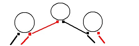
Each tweeter is getting an AC signal;  it alternates from neg to pos to neg to pos etc.  This is true of any speaker in an audio system.  When you look at the wiring as displayed here, you see that the left tweeter neg meets a 4 ohm load, and that the right tweeter pos meets a 4 ohm load.  What do the other two wires meet?

Right, a 4 ohm driver and 6 ohm driver that are parallel-connected, which is a 2.4 ohm load.  https://www.the12volt.com/caraudio/boxcalcs.asp

How do you suppose that's going to sound like?  For basics, the crossover is designed to match the given tweeter to the mid, and it's also designed to separate frequencies according to a given impedance.  That impedance is designed for 4 ohms.  Look at https://www.the12volt.com/caraudio/cross.asp, specifically at high pass crossovers and the charts for 4 ohm and for 2 ohm.  You see that the values are completely different according to the intended load impedance.  The result from this wiring configuration, in this sense, would be that the crossover would fluctuate between two different crossover frequencies.  To add insult to injury, the imaging would be severely smeared as right and left signals would coincide in the center.  Negative result:  sound like ass.

Your front soundstage problem arises from the result of the tweeter being too far away from the mid, and firing in a different plane.  I don't understand how you are pleased with sound and accuracy, but are not pleased with the soundstage...as these principles are intertwined.  Reposition the tweeters and do it without cutting holes.  Tweeters can usually be attached with a glue-type substance. 

Build the box so that it performs well in the worst case scenario and, in return, it will reward you at all times.
DYohn 
Moderator - Posts: 10,741
Moderator spaceThis member has made a donation to the12volt.com. Click here for more info.spaceThis member has been recognized as an authority in Electrical Theory. Click here for more info.spaceThis member has been recognized as an authority in Mobile Audio and Video. Click here for more info.spacespace
Joined: April 22, 2003
Location: Arizona, United States
Posted: June 03, 2006 at 8:35 PM / IP Logged  

Err...ahh... what you are proposing is not a good idea.  Here's the way to do it correctily (note that the signal comes from both + speaker outputs):

Briding center channel speaker - Last Post -- posted image.

Left Speaker                                        Center Speaker                                                Right Speaker

Support the12volt.com
geepherder 
Platinum - Posts: 3,668
Platinum spaceThis member consistently provides reliable informationspace
Joined: October 27, 2003
Posted: June 04, 2006 at 1:11 PM / IP Logged  
That's cool Dave.  Just for clarification, GND is an audio ground- the outer conductor of the rca, correct?  Obviously we wouldn't connect a speaker output to chassis ground.
My ex once told me I have a perfect face for radio.
DYohn 
Moderator - Posts: 10,741
Moderator spaceThis member has made a donation to the12volt.com. Click here for more info.spaceThis member has been recognized as an authority in Electrical Theory. Click here for more info.spaceThis member has been recognized as an authority in Mobile Audio and Video. Click here for more info.spacespace
Joined: April 22, 2003
Location: Arizona, United States
Posted: June 04, 2006 at 1:25 PM / IP Logged  
Yes, sorry, GND is the RCA shield ground and is NOT connected to a speaker output.
Support the12volt.com

Sorry, you can NOT post a reply.
This topic is closed.

  Printable version Printable version Post ReplyPost New Topic
You cannot post new topics in this forum
You cannot reply to topics in this forum
You cannot delete your posts in this forum
You cannot edit your posts in this forum
You cannot create polls in this forum
You cannot vote in polls in this forum

  •  
Search the12volt.com
Follow the12volt.com Follow the12volt.com on Facebook
Sunday, April 28, 2024 • Copyright © 1999-2024 the12volt.com, All Rights Reserved Privacy Policy & Use of Cookies
Disclaimer: *All information on this site ( the12volt.com ) is provided "as is" without any warranty of any kind, either expressed or implied, including but not limited to fitness for a particular use. Any user assumes the entire risk as to the accuracy and use of this information. Please verify all wire colors and diagrams before applying any information.

Secured by Sectigo
the12volt.com spacer
Support the12volt.com
Top
the12volt.com spacer