the12volt.com spacer
icon

4 prong relay


Post ReplyPost New Topic
< Prev Topic Next Topic >
hotwaterwizard 
Silver - Posts: 1,350
Silver spacespace
Joined: December 11, 2003
Location: California, United States
Posted: October 28, 2006 at 1:49 AM / IP Logged  
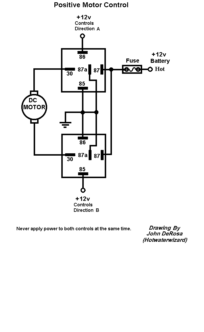
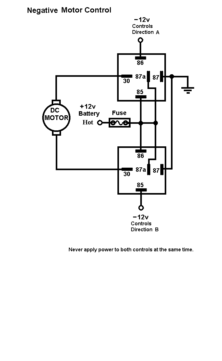
4 prong relay - Page 2 -- posted image.
John DeRosa (Hotwaterwizard)
Stockton California
When in doubt, try it out !
hotwaterwizard 
Silver - Posts: 1,350
Silver spacespace
Joined: December 11, 2003
Location: California, United States
Posted: October 28, 2006 at 1:49 AM / IP Logged  
4 prong relay - Page 2 -- posted image.
John DeRosa (Hotwaterwizard)
Stockton California
When in doubt, try it out !
master5 
Silver - Posts: 1,123
Silver spacespace
Joined: October 10, 2006
Location: United States
Posted: October 28, 2006 at 11:37 AM / IP Logged  

Excellent, you showed several ways to do this. Most likely the negative control will be used but many systems put out both on the doorlock outputs so either may work,

Although there would be no point to applying power to both controls, and the system itself , and any switches used if functioning properly would not do this, it actually wouldn't do any harm. It would simply send 12+ to both legs of the actuator and no current would flow, similar but the opposite of what it is doing in its "at rest" state, each leg is recieving 12- with no harm. (or vice-versa), it just wouldn't operate the actuator.

In the 3rd diagram (negative control motor) although this would work,  IMO I prefer to not ever have the legs rest at 12v positive since these run from the relays, through the door jams, into the doors. Too many risks of a short to ground. (blown fuses or worse if installed improperly) In addition, any manual switch(es) installed to operate the locks as well, can be negative, hence less running of "live" 12v +power throughout the vehicle.  I would prefer to use diagram 1. As long as one side of the relay coils are on 12+ constant, a negative on the other will activate the relay.

Blt79 
Member - Posts: 13
Member spacespace
Joined: September 19, 2004
Location: United States
Posted: November 04, 2006 at 1:01 PM / IP Logged  
ok I get this diagram for 1 actuator, but how would you wire 2 relays for 2 actuators?
hotwaterwizard 
Silver - Posts: 1,350
Silver spacespace
Joined: December 11, 2003
Location: California, United States
Posted: November 04, 2006 at 3:30 PM / IP Logged  
Doing the same thing you just put the Actuators across eachother in Parallel. Like you would a speaker Positve to Positive Negitive to Negitive.
John DeRosa (Hotwaterwizard)
Stockton California
When in doubt, try it out !
Page of 2

Sorry, you can NOT post a reply.
This topic is closed.

  Printable version Printable version Post ReplyPost New Topic
You cannot post new topics in this forum
You cannot reply to topics in this forum
You cannot delete your posts in this forum
You cannot edit your posts in this forum
You cannot create polls in this forum
You cannot vote in polls in this forum

  •  
Search the12volt.com
Follow the12volt.com Follow the12volt.com on Facebook
Thursday, May 30, 2024 • Copyright © 1999-2024 the12volt.com, All Rights Reserved Privacy Policy & Use of Cookies
Disclaimer: *All information on this site ( the12volt.com ) is provided "as is" without any warranty of any kind, either expressed or implied, including but not limited to fitness for a particular use. Any user assumes the entire risk as to the accuracy and use of this information. Please verify all wire colors and diagrams before applying any information.

Secured by Sectigo
the12volt.com spacer
Support the12volt.com
Top
the12volt.com spacer