the12volt.com spacer
icon

blown alpine mrd m605 amp


Post ReplyPost New Topic
< Prev Topic Next Topic >
wykdfantasy 
Member - Posts: 38
Member spacespace
Joined: July 27, 2006
Location: Florida, United States
Posted: December 29, 2009 at 12:32 AM / IP Logged  
I have an Alpine MRD-M605 amp that was wired up and working just fine for a few days. Today it worked up until the time I turned my truck off and when I turned it back on no more thump.
The blue LCD display on top just blinks on and off, and does not display any messages at all. I checked all connections, all are good, tested voltage with the multimeter, all is well up to the amp. So I took it apart. There does not appear to be any burnt smell, or bulging or leaking capacitors.
I did notice that one of the MOSFETS on the side had a leg that was broken, I am not sure if I broke it while taking it apart or if it damaged earlier today, however I soldiered it back together and retested the amp with no success.
Please let me know what would be the next step to check out on this amp.
i am an idiot 
Platinum - Posts: 13,667
Platinum spaceThis member consistently provides reliable informationspace
Joined: September 21, 2006
Location: Louisiana, United States
Posted: December 29, 2009 at 8:00 AM / IP Logged  
What are the numbers that are on the transistor with the broken leg?   Pu that info at diyaudio also.  Ir will speed up the process there also.  I will be at work all day, Perry will be of more help to you today.
wykdfantasy 
Member - Posts: 38
Member spacespace
Joined: July 27, 2006
Location: Florida, United States
Posted: December 29, 2009 at 10:37 AM / IP Logged  
The transistor that had the broken leg that I soldered back together is IRF540N
wykdfantasy 
Member - Posts: 38
Member spacespace
Joined: July 27, 2006
Location: Florida, United States
Posted: December 29, 2009 at 11:05 AM / IP Logged  
Here is some different info I collected at the request of one of the diyaudio members:
On the MOSFETS which are on the sides of the amp where the power leads hook up part number IRF3205, my multimeter reads 0 ohms between legs 1 + 2, and 2 + 3, but reads high numbers on 1 + 3, on all of them.
On the MOSFETS which are on the side of the amp where the speaker output terminals are part number IRF540N, my multimeter reads various numbers on all leg combinations on all of them.
On the output transistors on what would be the front side of the amp, I have 5 transistors, 4 different ones and 1 duplicate one. The tests as follows:
FRH20A15:
Leg 1 + 3 = .1 ohm
Leg 1 + 2 = 1.5 ohm
Leg 2 + 3 = Various numbers all over 1 ohm
RF2001:
Leg 1 + 3 = .1 ohm
Leg 1 + 2 = 4 ohm
Leg 2 + 3 = 4 ohm
C3421:
Leg 1 + 3 = Various numbers all over 1 ohm
Leg 1 + 2 = Various numbers all over 1 ohm
Leg 2 + 3 = Various numbers all over 1 ohm
A1358:
Leg 1 + 3 = Various numbers all over 1 ohm
Leg 1 + 2 = Various numbers all over 1 ohm
Leg 2 + 3 = Various numbers all over 1 ohm
C3421:
Leg 1 + 3 = Various numbers all over 1 ohm
Leg 1 + 2 = Various numbers all over 1 ohm
Leg 2 + 3 = Various numbers all over 1 ohm
i am an idiot 
Platinum - Posts: 13,667
Platinum spaceThis member consistently provides reliable informationspace
Joined: September 21, 2006
Location: Louisiana, United States
Posted: December 29, 2009 at 9:04 PM / IP Logged  

Does your meter have a diode test function.  It will be the only diagram on the selection wheel?    It will look a lot like this.

blown alpine mrd m605 amp -- posted image.

Set the meter to that setting and recheck the transistors and post those numbers.  If it were the left leg that broke off of the 540, that would cause problems.  Remove that transistor and see if it powers up then.  Mount all transistors back to the heat sink and insert a single 10 amp fuse in one of the fuse spots. 

i am an idiot 
Platinum - Posts: 13,667
Platinum spaceThis member consistently provides reliable informationspace
Joined: September 21, 2006
Location: Louisiana, United States
Posted: December 29, 2009 at 9:24 PM / IP Logged  
Do not pull the 3205s out of the board.  Unless you know they are bad.  If you do have to remove a transistor from the board, please follow these simple steps.  I know it goes against all that you think should happen, but trust me it will make it a lot easier for you.  Put as much solder as you can get on the 3 joints of the transistor to be removed.  Using a pair of needlenose or small pliers, grab the tab of the transistor.  Do not pull them out of the hole when the time comes, the pliers are only so you do not leave your fingerprints on the tab of the transistor.  It is going to get really really hot.  Once you have solder on all3 joints, lay your soldering iron  across all 3 joints, on the under side of the board.  Depending on the quality of your iron it may take 20 seconds to get all 3 joints molten.  Once they are all liquid, gently rock the transistor out of the board.  Once removed, now is the time to use the solder sucker or decoldering braid.  If you have to buy a solder sucker, purchase an EDSYN Soldapullt device.  If you have to buy a soldering iron buy a WELLER.  The extra solder makes it easier to get the part out.  It greatly reduces the chance of damaging the circuit board. 
wykdfantasy 
Member - Posts: 38
Member spacespace
Joined: July 27, 2006
Location: Florida, United States
Posted: December 30, 2009 at 9:38 AM / IP Logged  
Thank you for all that info, I have to run out of town today, so I wont be able to test today, but will check them as soon as I get back and let ya'll know how it went.
wykdfantasy 
Member - Posts: 38
Member spacespace
Joined: July 27, 2006
Location: Florida, United States
Posted: January 04, 2010 at 3:16 PM / IP Logged  
ok with the tester set on the buzzer function, the 3205's all switch as they should. When the tester leads are placed on a leg, it will beeep and then stop, meaning it switched, and switch legs, and again will beep then stop until i switch legs again, back and forth. So all (4) 3205's are switching ok.
The 540's if i touch leg 2 + 3 they will switch, much faster than the 3205's, its a very small fast blip on the buzzer. But all seem to switch consistently although two of them seem to be not as responsive as the rest, but do switch.
The single RF2001T2D switches just fine.
The single FRH20A15 switches just fine.
blown alpine mrd m605 amp -- posted image.
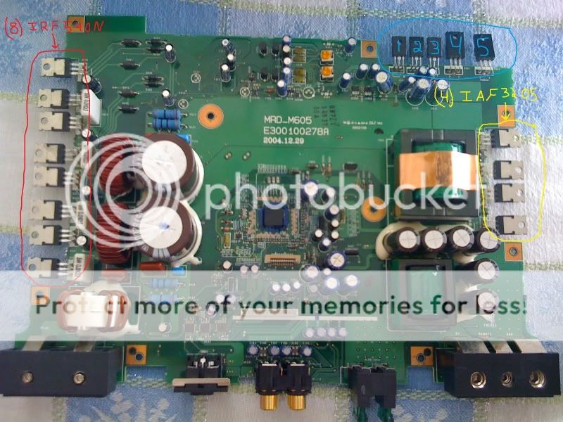
Here is a shot of the board, I have highlighted where the different banks of transistors are.
The red are the 540's
The yellow are the 3205's
The blue are as follows:
1:2SC3421
2:2SA1358
3:2SC3421
4:RF2001T2D
5:FRH20A15
i am an idiot 
Platinum - Posts: 13,667
Platinum spaceThis member consistently provides reliable informationspace
Joined: September 21, 2006
Location: Louisiana, United States
Posted: January 04, 2010 at 6:23 PM / IP Logged  
You stated earlier that the leg was broken on one of the 540s.  Which leg was broken.  If it was the left most leg, (Top Leg in your picture)  that would be a problem.  If it was the left leg, remove that transistor and mount the amp back to the heat sink, place a single 10 amp fuse in only one fuse holder, power it back up and let me know what happens then.
wykdfantasy 
Member - Posts: 38
Member spacespace
Joined: July 27, 2006
Location: Florida, United States
Posted: January 04, 2010 at 6:47 PM / IP Logged  
OK will do, it was the 3rd one down from the top how it is pictured in this photo, and it would be the top leg on that transistor which is leg #1.
OK, just to make sure I understand correctly, I will remove the whole transistor completely from the board, remove both 30 amp fuses, and replace just one of them with a 10 amp fuse and power it up, please let me know if I got that right, I don't want to misunderstand and cause further damage.
Page of 3

  Printable version Printable version Post ReplyPost New Topic
You cannot post new topics in this forum
You cannot reply to topics in this forum
You cannot delete your posts in this forum
You cannot edit your posts in this forum
You cannot create polls in this forum
You cannot vote in polls in this forum

  •  
Search the12volt.com
Follow the12volt.com Follow the12volt.com on Facebook
Saturday, April 20, 2024 • Copyright © 1999-2024 the12volt.com, All Rights Reserved Privacy Policy & Use of Cookies
Disclaimer: *All information on this site ( the12volt.com ) is provided "as is" without any warranty of any kind, either expressed or implied, including but not limited to fitness for a particular use. Any user assumes the entire risk as to the accuracy and use of this information. Please verify all wire colors and diagrams before applying any information.

Secured by Sectigo
the12volt.com spacer
Support the12volt.com
Top
the12volt.com spacer