the12volt.com spacer
icon

battery isolator vs cont duty solenoid


Post ReplyPost New Topic
< Prev Topic Next Topic >
stevekran 
Member - Posts: 2
Member spacespace
Joined: February 10, 2011
Location: South Carolina, United States
Posted: February 10, 2011 at 6:18 PM / IP Logged  
Ok, I've searched for the last 2 days and haven't been able to find an exact answer to the question I have. I've learned a lot while reading some of yall's posts, but haven't been able to figure out my problem.
I'm installing a stereo in a friend's jeep wrangler. It's certainly over the top, but this kid is made outta money.
Here's an overview:
1987 Jeep Wrangler without backseat
Marine Sony head unit with wired remote
4x6 infinity speakers in dash
6" JL component set in sound bar
2 sets of JL 6x9's in the rear
1 JL 13w7
1-1000/1v2 JL sub amp
2-300/4v2 JL amps for mids/highs
1-2 Farad hybrid Rockford Fosgate Cap
There's a list of the components I've got so far....I'm working on getting an upgraded alternator from a local shop that specializes building them custom.
I want to use an extra battery and put it in the rear of the vehicle. I'm going to run the winch and fog lights, and whatever accessories for it off that dedicated battery. I plan on keeping the stock starting battery as is.
I understand that you don't want two 'different' batteries in parallel because one will eventually kill the other. I understand that a diode based battery isolator will keep the two batteries electrically isolated, BUT in turn will create a voltage drop of .7 volts across the diode resulting in less voltage to your amplifiers.
Here's what I don't understand/question....
If I use a continuous duty solenoid instead of a battery isolator, will the batteries be connected in parallel with the vehicle running? If so, then will it matter if the batteries are different sizes while they are getting charged from the alternator?
I WOULD run two of the same batteries, but there is limited space under the hood.
If I didn't make that clear enough just let me know and I'll try to explain it further.
Thanks for the help
-Steve
oldspark 
Gold - Posts: 4,913
Gold spacespace
Joined: November 03, 2008
Location: Australia
Posted: February 10, 2011 at 11:04 PM / IP Logged  
When charging, there is no problem having paralleled batteries of different size, age, etc. (Assuming your situation - ie, not tiny and HUGE; reasonable alternator/charger size; etc.)
To an extent, the same applies when in use (discharging) - but that isn't really a concern....
The common solution - an "isolator" that connects the batteries when charging, and otherwise isolates the batteries.   
IE - normal main battery & alternator. The relay/isolator connects the 2nd battery when charging.
How? Smart Battery Isolator maybe?
Better still - if you have a charge lamp, let the charge lamp circuit control the isolation relay.
This is now being nicknamed the UIBI (you-bee) Ultimate Intelligence Battery Isolator. (Search my posts hereon...)
Whilst most alternators with charge-Lamp circuits (aka D+ or L terminals) can power a typical automotive relay (eg, 60Ohm/200mA coil), larger relays for 200A or 400A may require 1A-2A coil current.
In that case, use a smaller relay to drive the BIG relay. (Or use a MOSFET or transistor as a buffer.)
Operational Summary:
If IGN is off, then isolator is open (2nd battery is isolated).
If charge lamp is on, then isolator is open.
If charge lamp is off, then isolator is closed (batteries connected & charging) [unless charge light is faulty; isolator is the closed if the alternator is charging, open if not - ie, the charge light itself is not required for the UIBI, though it is probably required to guarantee charging!].
Interested? Confused?
The relay/isolator #30 & #87 is connected between the two battery's +12V terminals as normal (with a circuit breaker or fuse at each end as near each battery as possible).
The coil+ #86 is connected to the D+ or L circuit/terminal on the alternator (ie, its regulator).
The coil- #85 is to GND.
PS - keeping the original cranking battery and adding a second battery of your choice (near the amp etc) - CONGRATULATIONS! So many change the main battery to an AGM (as well) for little gain and usually great expense - especially if they do not like cranking!
stevekran 
Member - Posts: 2
Member spacespace
Joined: February 10, 2011
Location: South Carolina, United States
Posted: February 11, 2011 at 12:13 AM / IP Logged  
Well the stock battery is fairly small compared to the aux battery I'm looking at. I'm looking at a Kinetik HC-2400. Any other suggestions or comments?
BTW, thanks for what you've already posted. That in itself is a big help, but I don't fully understand the 'charge lamp circuit' you are referring to. Could you break that down a little more for me?
Thanks
oldspark 
Gold - Posts: 4,913
Gold spacespace
Joined: November 03, 2008
Location: Australia
Posted: February 11, 2011 at 12:51 AM / IP Logged  
A schematic of a traditional charge lamp circuit:
battery isolator vs cont duty solenoid -- posted image.
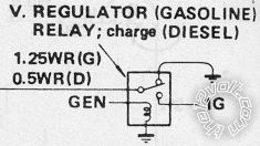
When the generator (alternator) charges, it toggles the charge-Lamp (D+ or L; the LHS WR White-Red wire) from GND to IG +12V.
That connects to #86 of the relay.
As usual I can't find my 12V posts with diagrams, but there are descriptions (search "UIBI").
There are other sites with figs, but I'll have to find them later.
No other suggestions. Unless you do NOT have a charge-lamp circuit (which most typical (older) alternators do have), them IMO the UIBI is the most reliable & best as well as the cheapest.
oldspark 
Gold - Posts: 4,913
Gold spacespace
Joined: November 03, 2008
Location: Australia
Posted: February 11, 2011 at 3:02 PM / IP Logged  
stevekran wrote:
...I'm working on getting an upgraded alternator from a local shop that specializes building them custom.
Be wary - rewound standards often cannot handle overload thermals nor do they have "normal" self-protection. Many rewinds seem to blow under stress.
Consider properly designed HO alternators instead. (EG - alternators SHOULD handle jump starts etc and be self-limiting wrt over-current etc.)

Sorry, you can NOT post a reply.
This topic is closed.

  Printable version Printable version Post ReplyPost New Topic
You cannot post new topics in this forum
You cannot reply to topics in this forum
You cannot delete your posts in this forum
You cannot edit your posts in this forum
You cannot create polls in this forum
You cannot vote in polls in this forum

  •  
Search the12volt.com
Follow the12volt.com Follow the12volt.com on Facebook
Wednesday, May 29, 2024 • Copyright © 1999-2024 the12volt.com, All Rights Reserved Privacy Policy & Use of Cookies
Disclaimer: *All information on this site ( the12volt.com ) is provided "as is" without any warranty of any kind, either expressed or implied, including but not limited to fitness for a particular use. Any user assumes the entire risk as to the accuracy and use of this information. Please verify all wire colors and diagrams before applying any information.

Secured by Sectigo
the12volt.com spacer
Support the12volt.com
Top
the12volt.com spacer