the12volt.com spacer
icon

two batteries


Post ReplyPost New Topic
< Prev Topic Next Topic >
08canyon 
Member - Posts: 24
Member spacespace
Joined: December 02, 2009
Location: Michigan, United States
Posted: February 03, 2010 at 8:06 PM / IP Logged  
OK.... I have a 2008 GMC Canyon I am installing a Kicker 1000.1 and a Kicker 350.2 amp. I am installing a Kinetik HC1400 or HC1800 (depending on which one will fit). I am anticipating the need for a secondary battery as well. I read on here (searched and cannot find it) that somebody bought a Walmart battery and wired it up as a secondary battery. I was looking at a Kinetik HC600, it'll fit perfectly behind the seats. I have no plans to run the system without the truck running. Can I do it with dissimilar sized batteries? Do I wire it up like I would a cap? Do I need an isolator?
Thanks again.
whiterob 
Copper - Posts: 351
Copper spacespace
Joined: July 22, 2007
Location: United States
Posted: February 03, 2010 at 11:38 PM / IP Logged  
Two batteries is not going to do much for you if you do not plan on running your system with the truck off like you said. If you have power issues then you should look into getting a high output alternator and big 3 upgrade. An upgraded battery (over a stock battery) can have some benefit but the alternator and big 3 are going to be FAR more beneficial. A second battery will just put more of a demand on your electrical system which can actually worsen any power issues you may be having.
If you do run two batteries you will want to make sure they are the same. They should be EXACTLY the same as any small differences can lead to shortened life of one or both of the batteries. You will wire them in parallel and do not need an isolator.
oldspark 
Gold - Posts: 4,913
Gold spacespace
Joined: November 03, 2008
Location: Australia
Posted: February 04, 2010 at 3:55 AM / IP Logged  
Agreed that batteries will not change insufficient supply.
Ideally the alternator will supply sufficient power to handle all loads.
As above, if paralleled, batteries should (must!!) be matched, but IMO it still shouldn't be done without safeguards.
And with 2 matched batteries - one in the engine bay and one elsewhere - they will no longer be matched.
Besides, eventually one will start to fail and that's when the problems begin - especially if they are AGMs!
Instead, for 2 battery setups, the AGM should be with the amp - close enough so that a cap isn't needed.   
The main battery can be retained.
The audio battery is only connected to the alternator (or main battery) when the vehicle is charging. Exactly how depends on various capacities (alt, amp, battery(s)).
However added batteries (even caps!) do not "add a load" to the electrical system - in fact they tend to take the strain off the alternator etc.
There may be added alternator load to recharge them, but that does not strain the alternator.
Besides, that is returned by the added battery capacity during discharge.
And since the battery discharge voltage drops will be lower, that means less charge current per battery.   
Just remember, batteries and capacitors do NOT magically generate power. (They are stores for power after being charged.)
Alternators generate power (via fuel conversion) to power loads and charge storage elements.
08canyon 
Member - Posts: 24
Member spacespace
Joined: December 02, 2009
Location: Michigan, United States
Posted: February 04, 2010 at 9:30 AM / IP Logged  
Hmmm... OK. Thanks guys. I thought that thats what the HC600 was designed for, to be wired near the amps like a cap would be.
08canyon 
Member - Posts: 24
Member spacespace
Joined: December 02, 2009
Location: Michigan, United States
Posted: February 04, 2010 at 9:36 AM / IP Logged  
Ahhh.... found it. Heres the thread I referenced.
https://www.the12volt.com/installbay/forum_posts.asp~TID~119473~get~last
This is what I wanted to do.
whiterob 
Copper - Posts: 351
Copper spacespace
Joined: July 22, 2007
Location: United States
Posted: February 04, 2010 at 1:19 PM / IP Logged  
oldspark wrote:
However added batteries (even caps!) do not "add a load" to the electrical system - in fact they tend to take the strain off the alternator etc.
There may be added alternator load to recharge them, but that does not strain the alternator.
Besides, that is returned by the added battery capacity during discharge.
And since the battery discharge voltage drops will be lower, that means less charge current per battery.
I agree with most of what you said but this point I think I have to disagree with. A second battery or cap is going to have a some internal resistance. More power is going to be going to it then is going to come from it as no device is going to be 100% efficient. Although the amount of power a cap or battery may actually use is very small it is still less than what you started with. So basically your alternator is going to need to produce more power than it would without these devices which is why I say it is more of a "strain".
A battery is going to need to be kept charged so having two batteries will have mean now the alternator needs to keep two batteries charged over one. This is not very difficult when both batteries are fully charged. The problem can arise when your batteries are drained. If you are running your stereo and the alternator cannot keep up with the demand your batteries will be constantly drained. Now you are asking the alternator to charge both batteries and still keep up with the regular demand. This will mean a much larger demand on your alternator. So in some cases the strain can be great on the alternator.
tommy... 
Gold - Posts: 1,901
Gold spacespace
Joined: December 10, 2004
Location: United States
Posted: February 04, 2010 at 2:28 PM / IP Logged  
Battery Isolators:
Many people listen to their stereo without the engine running. This often leads to dead batteries and a vehicle that won't start. A battery isolator will let you completely discharge one battery without discharging the starting battery.
Different Types of Isolators:
There are 2 main types of battery isolators. The diode based type and the relay (solenoid) type.
Diode Based Isolator:
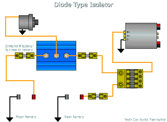
This type of isolator is basically two very high current diodes in a heat sink. The diode based isolator has the advantage of long life and trouble free operation but many of the diode based isolators cause a .4 to .6 volt loss which means that the batteries will not charge to as high a voltage as when they are connected directly to the alternator. The diagram below shows the connection for the diode based isolator. Some diode type isolators have a fourth terminal which controls the current flow through the device.

two batteries -- posted image.


Solenoid Based Isolators:
This type of isolator uses large high current relays to control the flow of current. The diagram below shows two solenoids. Solenoid A determines whether the second battery is connected to the rest of the charging system or not. Solenoid B connects the second battery to the distribution block. The second solenoid allows a complete disconnect from the amplifiers for safety. The diodes connected in parallel to the solenoid's coils are used to protect switch A and switch B from inductive kickback when the solenoid's coils are de-energized. The advantage of the solenoid based isolator is that there is virtually no voltage loss across the contacts. The main disadvantage is that the reliability isn't quite as good as the diode based isolator.
The coil of the solenoid will draw significantly more current than can safely be supplied by the remote/power antenna output of your head unit. You should NOT connect them directly to the head unit. You need to use a relay to buffer the remote/power antenna output of the head unit so that the head unit's switching transistor isn't damaged.
In the demo below, click on the head unit to switch it on and off. Click on either side of the toggle switch to change its position. The round green dots are voltage indicators. They are dark when there is no voltage and bright when voltage is present. The arrows indicate current flow through the respective part of the circuit. Switch A allows you to disconnect the main starting battery from the rear battery and amplifiers. This allows you to play the amplifier without fear of draining the starting battery. When switch B is off, the solenoid B is off (disconnected) and you can work on the amplifier's main power wiring without fear of shorting battery power to ground.

NOTE:
There are 2 types of solenoids. They look virtually identical but are designed for different uses.
Ford Type Solenoid:
If you're familiar with older Ford vehicles, you've no doubt seen the fender mounted solenoid. It's used to make/break the connection from the battery to the starter. This solenoid is designed to pass as much as 400 amps of current but only for a short period of time. The solenoid's magnetic coil has only 3-4 ohms of resistance. If used for continuous duty, the coil will overheat and fail. The low resistance provides higher the contact pressure that's needed to keep the contact resistance to a minimum.
Continuous Duty Solenoids:
For main power switching in car audio, you need a continuous duty solenoid. These solenoids will have approximately 15-30 ohms of resistance across the coil. As you can imagine, this will allow the coil to run much cooler than the starter solenoid mentioned above (although the solenoid will be quite warm after a while). The solenoid I've used is the White-Rogers 70-111224-5. It's available from Grainger or virtually any auto parts supplier. It's rated at 80 amps continuous and can take short periods of higher current flow. I've been using one on my test bench where I draw more than 100 amps through it for 20 minutes at a time and it hasn't failed yet.


Adding a second battery without using an isolator:
Some people have good results when they add a second battery to their system. Especially if the second battery is close to their amplifiers. If you want to add a second battery, there are a few things that you should know.

  1. the battery is inside the passenger (in a hatchback vehicle or in a car with a back seat that folds down), you must use a sealed battery (i.e. Optima). If the battery is being used in the trunk of a vehicle you can use a standard battery but you will need put the battery in a battery box and you will need to provide proper ventillation. Proper ventillation would mean forced air (fan) ventilation from the battery box to the outside of the vehicle. When a standard lead acid battery charges, it produces flammable gases which must be removed from the vehicle to prevent a fire/explosion hazard.
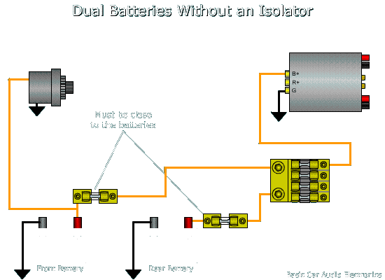
  2. The second battery must be fused. The fuse must be as close to the battery as possible (just as you have on the main battery). of the power for the system must flow through through the fuses (at the batteries) to protect against electrical fires. The diagram below shows the proper fusing and wiring. The fuse at the main battery must be properly rated to protect wire 'A'. The fuse at the second battery must be properly rated to protect wire 'B'.

    two batteries -- posted image.
  3. No matter what kind of battery you use, care be taken to assure that nothing can come in contact with the battery's terminals. I would strongly recommend putting the battery into a plastic battery box with a cover that can be secured onto the box.
  4. The ground for the second battery should be grounded to the floor pan of the vehicle. The floor pan is the main piece of sheet metal that forms the largest portion of most new vehicles. This will provide the best return path for the second battery.
M.E.C.P & First-Class
Go slow and drink lots of water...Procrastinators' Unite...Tomorrow!
oldspark 
Gold - Posts: 4,913
Gold spacespace
Joined: November 03, 2008
Location: Australia
Posted: February 04, 2010 at 6:06 PM / IP Logged  
Tommy's reply has good info.
I do not like the diode splitters for various reasons, but they have their application. But it may cause undercharging of the battery(s) and a lower system voltage.
And with the wiring in the fuse 2 battery setup, keep in mind the likely lower charging rate of the 2nd battery, but ignoring wiring losses it will eventually charge to the same level at the first battery (just slower).
Can't say the same with the diodes however - although both battery voltages depend on the two path resistances and loads in both cases, the diodes probably exhibit a greater voltage drop with increasing current.   
WhiteRod - such resistances have little effect.
A battery's & cap's internal resistance is usually way under 0.1 Ohm. Negligible. (The equivalent of a 12W bulb if across 12V - not that it is, but more later.)
The battery's float current is about 1% of its rated AH current, so that too is negligible.
For a battery, it is actually its charging inefficiency that is the biggest "extra load", but that is only after a discharge which means it has supplied power that the alternator hasn't.
IE - it did REDUCE the load on the alternator.
And as I pointed out elsewhere, the initial total recharge current for two batteries may be less than with one.
Why? Because the discharge voltage is lower, hence lower initial recharge current.
In simple theory, the recharge current will be the same for one battery as with 2, or 10. But batteries are not linear, nor simple.
[But caps are - do the calcs and see the difference - the only "extra" power is the current through the caps ESR which is typically 10 milli-Ohm - a mere 100W for a few seconds if the cap can take 100A!! Not that caps are (or need be) used in most decent systems... And a battery won't absorb 100A (for long, else shouldn't!)]
So the extra "strain" on an alternator is a few percent.
The "strain" it saves the alternator can be much higher - ie several times the altenator's rating.   
But the point is - ignore stuff about the extra strain of more batteries and caps.
If that were a concern, we would all be using the smallest battery we could. And probably be using hand-cranks too!
PS - a almost embarrassing omission from above....
Of course any added resistance such as ESR REDUCES the current in the added component thereby reducing its "load" on the system.
IE - ESR etc reduces loads - it does no increase them.
But I did go on to explain "the real situation".
But any argument that uses ESR or added resistance as an "added load" argument can be dismissed (it's the opposite that is true!).

Sorry, you can NOT post a reply.
This topic is closed.

  Printable version Printable version Post ReplyPost New Topic
You cannot post new topics in this forum
You cannot reply to topics in this forum
You cannot delete your posts in this forum
You cannot edit your posts in this forum
You cannot create polls in this forum
You cannot vote in polls in this forum

  •  
Search the12volt.com
Follow the12volt.com Follow the12volt.com on Facebook
Thursday, October 31, 2024 • Copyright © 1999-2024 the12volt.com, All Rights Reserved Privacy Policy & Use of Cookies
Disclaimer: *All information on this site ( the12volt.com ) is provided "as is" without any warranty of any kind, either expressed or implied, including but not limited to fitness for a particular use. Any user assumes the entire risk as to the accuracy and use of this information. Please verify all wire colors and diagrams before applying any information.

Secured by Sectigo
the12volt.com spacer
Support the12volt.com
Top
the12volt.com spacer