the12volt.com spacer
icon

using the dei 528t on an existing alarm?


Post ReplyPost New Topic
< Prev Topic Next Topic >
restoman 
Member - Posts: 12
Member spacespace
Joined: May 07, 2010
Location: California, United States
Posted: May 07, 2010 at 2:16 PM / IP Logged  

Hello folks. New guy here with a question. (And please be kind. I know NOTHING about electronics.)

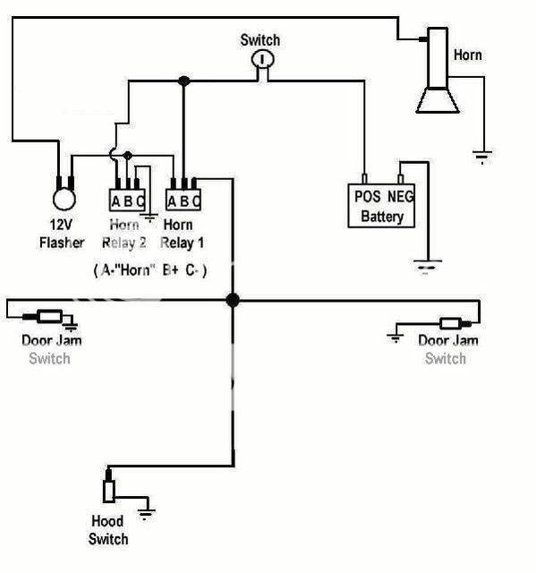
I have a 1969 Chevrolet Corvette that came with the optional horn alarm. This utilizes a key located on the tail panel to activate the alarm and a few relays, a flasher, a horn and a couple of door contacts. It's a really simple system. The problem is that when the doors are opened, the horn sounds FOREVER!! It's not like one of the newer alarms where they sound for 90 seconds and then reset. This one never shuts off and eventually drains the battery (and my neighbors)!
I have a friend that suggested I install a DEI 528T relay/timer and configure it so the alarm will go off for 90 seconds (or whatever I want), then automatically reset. However, when I got the relay/timer in the mail, I was shocked to see that the "instructions" (if you can call them that) are SADLY inadequate! (And that's being kind!!)
So anyway, my questions is can someone tell me how to hook this thing up to my alarm so I can keep what's left of my neighbors as friends?!
If you need more info, or a basic schematic of the existing alarm, let me know...
Thanks
Ed

howie ll 
Pot Metal - Posts: 16,466
Pot Metal spacespace
Joined: January 09, 2007
Location: United Kingdom
Posted: May 07, 2010 at 2:43 PM / IP Logged  
We would need to know if the key switch switches neg or pos to feed the alarm, or how is the horn fed? Via a relay and how is it wired. The info on the 528t is pretty simple for a pro, I've even used one to make a wash-wipe!
restoman 
Member - Posts: 12
Member spacespace
Joined: May 07, 2010
Location: California, United States
Posted: May 07, 2010 at 2:58 PM / IP Logged  

Howie, the key switch just ties the positive side of the battery to one of the relays. I've attached a drawing showing how the system works. Let me know if you need more info.

Ed

using the dei 528t on an existing alarm? -- posted image.

restoman 
Member - Posts: 12
Member spacespace
Joined: May 07, 2010
Location: California, United States
Posted: May 07, 2010 at 3:27 PM / IP Logged  

Sorry folks. The drawing I uploaded was too big, so I deleted it and uploaded a smaller one:

using the dei 528t on an existing alarm? -- posted image.

howie ll 
Pot Metal - Posts: 16,466
Pot Metal spacespace
Joined: January 09, 2007
Location: United Kingdom
Posted: May 07, 2010 at 5:18 PM / IP Logged  
Remove the 2 relays, then join red and black on the 528 to a 30amp fuse, red and black to a good ground, from the fuse, feed the switch wire then bring the other side of the switch to yellow on the 528t. Ignore the orange and bring the brown out to the flasher unit then feed the horn from the flasher units output. Run the BLACK/ white on the 528t to your contact switches, then set the timer for say 30 secs. You could also use another relay from the flasher out put to run your lights if desired.
lectricguy 
Copper - Posts: 359
Copper spacespace
Joined: March 18, 2008
Location: Rhode Island, United States
Posted: May 07, 2010 at 5:20 PM / IP Logged  

restoman-

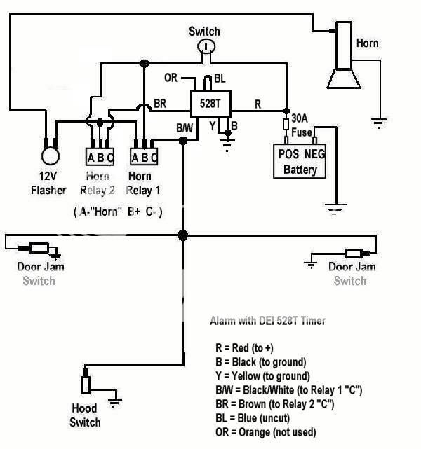
  From your diagram, it appears that Horn Relay 2 latches when Horn Relay 1 triggers.   I would use a 528T to connect the ground on Horn Relay 2 for the time you want the alarm to sound, and then break the ground.

 I would wire the 528T as follows:

Red to +12V

Black to Ground

Disconnect Horn Relay 2  terminal C  from ground

Yellow to Ground

Brown to Horn Relay 2  terminal C

Black with Stripe to Horn relay 1 Terminal C

Orange is not used.

Blue loop uncut (Negative Trigger).

Theory of Operation:

When the door pin is grounded (door opened) while the alarm is on, Horn Relay 1 will provide 12V to Horn Relay 2 and the flasher. 

At the same time, the 528T will receive a negative pulse from the door pin (from Black w/Stripe), and Brown and Yellow contacts will be connected for the timer setting time. 

Because  Horn Relay 2 will receive Ground on Terminal C  through the 528T Brown and Yellow, Horn Relay 2 will Turn on, providing power from its terminal A to Terminal B.

When the 528T Brown and Yellow contacts open as the timer completes its cycle, Horn Relay 2 opens and the alarm turns off.

Lectric Guy
lectricguy 
Copper - Posts: 359
Copper spacespace
Joined: March 18, 2008
Location: Rhode Island, United States
Posted: May 07, 2010 at 5:36 PM / IP Logged  
There are many ways to "skin the cat".  Howie's approach is also excellent, as it reduces the relays involved.   I attempted to simplify the wiring you need to do.  Either will work.
Lectric Guy
restoman 
Member - Posts: 12
Member spacespace
Joined: May 07, 2010
Location: California, United States
Posted: May 07, 2010 at 7:09 PM / IP Logged  

Thank you gentlemen! I don't have a 30 amp fuse in the fuse box, so it would have to be an in-line one coming directly from the battery, right? I wouldn't mind getting rid of a few relays, but I'm confused Howie. You said:

"Remove the 2 relays, then join red and black on the 528 to a 30amp fuse, red and black to a good ground"
You have red and black going to a 30 amp fuse AND to ground!! I don't know a lot about electronics, but I DO know you can't have both! Am I missing something here? My 528 has a solid red wire, a solid black wire, a solid orange wire, a solid brown wire, a solid yellow wire, a black wire with a white stripe and a small blue wire that comes out of the housing and then goes right back in again. Is mine different than the "norm"? A simple drawing showing what you mean would be great!
Lectric guy, your way appears to be the easiest way using the existing hardware, but I might go the other route since it removes parts that aren't really necessary with the 528. But if I get too confused, I'll go your route!!
Ed

restoman 
Member - Posts: 12
Member spacespace
Joined: May 07, 2010
Location: California, United States
Posted: May 09, 2010 at 7:12 PM / IP Logged  

Lectricguy, I modified my drawing per your instructions, but I'm not sure I got it right. Can you take a look and verify I have it correct?

Howie, can you give me a little more info on what I would need to do to get rid of the two relays? I like your idea better since it removes some componets, but I'm confused about the configuration.
Thanks again guys
Ed
using the dei 528t on an existing alarm? -- posted image.

lectricguy 
Copper - Posts: 359
Copper spacespace
Joined: March 18, 2008
Location: Rhode Island, United States
Posted: May 09, 2010 at 8:50 PM / IP Logged  

You have the diagram I described correct.  

For Howie's approach:

Disconnect Horn Relay 1 and 2

For 528T--

Red to +12V Fused and to the input side of the switch.

Yellow to the output side of the switch.

Brown to the Flasher input.

Black with Stripe to the Door Pin Switches.

Black to Ground.

Orange is not used.

Blue loop uncut (Negative Trigger).

Lectric Guy
Page of 3

  Printable version Printable version Post ReplyPost New Topic
You cannot post new topics in this forum
You cannot reply to topics in this forum
You cannot delete your posts in this forum
You cannot edit your posts in this forum
You cannot create polls in this forum
You cannot vote in polls in this forum

  •  
Search the12volt.com
Follow the12volt.com Follow the12volt.com on Facebook
Thursday, October 31, 2024 • Copyright © 1999-2024 the12volt.com, All Rights Reserved Privacy Policy & Use of Cookies
Disclaimer: *All information on this site ( the12volt.com ) is provided "as is" without any warranty of any kind, either expressed or implied, including but not limited to fitness for a particular use. Any user assumes the entire risk as to the accuracy and use of this information. Please verify all wire colors and diagrams before applying any information.

Secured by Sectigo
the12volt.com spacer
Support the12volt.com
Top
the12volt.com spacer