the12volt.com spacer
icon

subwoofer pops when turned off


Post ReplyPost New Topic
< Prev Topic Next Topic >
AaronD81 
Member - Posts: 14
Member spacespace
Joined: October 17, 2002
Location: United States
Posted: June 16, 2009 at 8:39 PM / IP Logged  
My subwoofer pops when I turn off the car, but not when I turn it on. Also, if I turn off the sub amp while it's still receiving a signal it doesn't pop. I've done some searching and found some info on delay circuits that keep the signal source on for a second or so longer than the subwoofer amplifier. The how-to from Crutchfield only describes the diode and cap, but the diagram shows a transistor and relay, which is correct?
http://www.crutchfield.com/S-Pl4IZ8wECqa/tech/kb327.html
Also, this post only describes using a diode and cap.
https://www.the12volt.com/installbay/forum_posts.asp?tid=7885&KW=turn+on+pop+velocity
i am an idiot 
Platinum - Posts: 13,693
Platinum spaceThis member consistently provides reliable informationspace
Joined: September 21, 2006
Location: Louisiana, United States
Posted: June 16, 2009 at 8:58 PM / IP Logged  

What kind of vehicle?  What year?   Factory or aftermarket radio?

AaronD81 
Member - Posts: 14
Member spacespace
Joined: October 17, 2002
Location: United States
Posted: June 16, 2009 at 9:06 PM / IP Logged  
1998 Volvo V70, aftermarket head unit and subwoofer.
i am an idiot 
Platinum - Posts: 13,693
Platinum spaceThis member consistently provides reliable informationspace
Joined: September 21, 2006
Location: Louisiana, United States
Posted: June 16, 2009 at 9:19 PM / IP Logged  

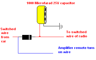
Is the remote turn on of the amp connected to the Amp Turn on wire of the radio?

subwoofer pops when turned off -- posted image.

AaronD81 
Member - Posts: 14
Member spacespace
Joined: October 17, 2002
Location: United States
Posted: June 16, 2009 at 9:37 PM / IP Logged  
I tried it connected to a switched wire from the car and the remote turn on on the head unit, no difference. So according to your diagram I just need the diode and cap?
AaronD81 
Member - Posts: 14
Member spacespace
Joined: October 17, 2002
Location: United States
Posted: June 17, 2009 at 3:45 PM / IP Logged  
I tried the circuit in your diagram and it keeps burning up (literally) the capacitor. The one I used was 470uf 35v based on the crutchfield explanation.
i am an idiot 
Platinum - Posts: 13,693
Platinum spaceThis member consistently provides reliable informationspace
Joined: September 21, 2006
Location: Louisiana, United States
Posted: June 17, 2009 at 3:57 PM / IP Logged  
You have the capacitor connected backwards.  There shoud be markings on the side that signify the negative terminal.  Make sure you have the negative terminal of the capacitor connected to ground.   If it is heating up, this is the only thing that can cause that.
AaronD81 
Member - Posts: 14
Member spacespace
Joined: October 17, 2002
Location: United States
Posted: June 17, 2009 at 4:09 PM / IP Logged  
Thanks, now I feel like an idiot.
i am an idiot 
Platinum - Posts: 13,693
Platinum spaceThis member consistently provides reliable informationspace
Joined: September 21, 2006
Location: Louisiana, United States
Posted: June 17, 2009 at 4:22 PM / IP Logged  

Let us know if you get it working.

AaronD81 
Member - Posts: 14
Member spacespace
Joined: October 17, 2002
Location: United States
Posted: June 23, 2009 at 1:46 PM / IP Logged  
Works perfectly now, thanks.

Sorry, you can NOT post a reply.
This topic is closed.

  Printable version Printable version Post ReplyPost New Topic
You cannot post new topics in this forum
You cannot reply to topics in this forum
You cannot delete your posts in this forum
You cannot edit your posts in this forum
You cannot create polls in this forum
You cannot vote in polls in this forum

  •  
Search the12volt.com
Follow the12volt.com Follow the12volt.com on Facebook
Thursday, October 31, 2024 • Copyright © 1999-2024 the12volt.com, All Rights Reserved Privacy Policy & Use of Cookies
Disclaimer: *All information on this site ( the12volt.com ) is provided "as is" without any warranty of any kind, either expressed or implied, including but not limited to fitness for a particular use. Any user assumes the entire risk as to the accuracy and use of this information. Please verify all wire colors and diagrams before applying any information.

Secured by Sectigo
the12volt.com spacer
Support the12volt.com
Top
the12volt.com spacer