the12volt.com spacer
icon

neon light remote switch


Post ReplyPost New Topic
< Prev Topic Next Topic >
hndakd 
Member - Posts: 7
Member spacespace
Joined: November 28, 2004
Location: United States
Posted: November 29, 2004 at 12:23 AM / IP Logged  
hello everyone.  I frequent this site alot and have never created an a account.... just searched for info.  well i was asked to help a buddy of mine get his neon lights to run off of this remote he has.  i installed it and couldnt get it to work.  if you guys can give me an idea of what to do with this box id really appreciate it.  my main problem is that the signal wires are color coded but not with a polarity also.  like the grey wires are both grey i know i need a postive and negative to hook the lights up but which is positive and which is negative i dont know.  he had it working before i started to mess with it but it was all wired wierd and didnt work that well. heres a schematic
newb
hndakd 
Member - Posts: 7
Member spacespace
Joined: November 28, 2004
Location: United States
Posted: November 29, 2004 at 12:26 AM / IP Logged  
well i cant figure out how to add an attatchment and i dont have image hosting... damn
newb
auex 
Platinum - Posts: 5,041
Platinum spaceThis member has made a donation to the12volt.com. Click here for more info.spacespace
Joined: December 23, 2002
Location: Arizona, United States
Posted: November 29, 2004 at 12:34 AM / IP Logged  
neon light remote switch -- posted image.
Certified Security Specialist
Always check info with a digital multimeter.
I promise to be good.
Tell Darwin I sent you.
I've been sick lately, sorry I won't be on much.
hndakd 
Member - Posts: 7
Member spacespace
Joined: November 28, 2004
Location: United States
Posted: November 29, 2004 at 12:35 AM / IP Logged  

many thanks

newb
auex 
Platinum - Posts: 5,041
Platinum spaceThis member has made a donation to the12volt.com. Click here for more info.spacespace
Joined: December 23, 2002
Location: Arizona, United States
Posted: November 29, 2004 at 12:38 AM / IP Logged  
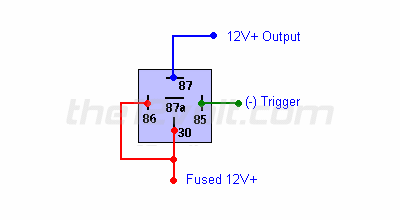
Well I don't quite understand your diagram. But basically to put a switch of any kind, toggle, momentary, or alarm output, to activate this is simple. First if the switch being used is a negative output then use this diagram
neon light remote switch -- posted image.
So basically wire the switch to the relay like this and then the output will be what turns the neons on.
Also to post images you must include the file extension, ".jpg".
Certified Security Specialist
Always check info with a digital multimeter.
I promise to be good.
Tell Darwin I sent you.
I've been sick lately, sorry I won't be on much.
hndakd 
Member - Posts: 7
Member spacespace
Joined: November 28, 2004
Location: United States
Posted: November 29, 2004 at 12:42 AM / IP Logged  

its not an alarm but remote unit. thats a copy of what is in the little instruction book.  those colored wires, blue, gray, green, and brown all go to the button signals on the remote.

newb
auex 
Platinum - Posts: 5,041
Platinum spaceThis member has made a donation to the12volt.com. Click here for more info.spacespace
Joined: December 23, 2002
Location: Arizona, United States
Posted: November 29, 2004 at 12:45 AM / IP Logged  
Ok, take one of the outputs and hook it up as pin 85 -trigger on the relay. Wire the rest as stated in the diagram and it should work. If it doesn't then either you aren't using the right output, output is blown, or something may be wrong with the neon. I would suggest that you try another output that you know is working to test. I noticed you said it was working and this is why I am saying to try another output.
Also make sure you have power at the relay and didn't blow the fuse.
Certified Security Specialist
Always check info with a digital multimeter.
I promise to be good.
Tell Darwin I sent you.
I've been sick lately, sorry I won't be on much.
hndakd 
Member - Posts: 7
Member spacespace
Joined: November 28, 2004
Location: United States
Posted: November 29, 2004 at 12:53 AM / IP Logged  

auex wrote:
Ok, take one of the outputs and hook it up as pin 85 -trigger on the relay. Wire the rest as stated in the diagram and it should work. If it doesn't then either you aren't using the right output, output is blown, or something may be wrong with the neon. I would suggest that you try another output that you know is working to test. I noticed you said it was working and this is why I am saying to try another output.
Also make sure you have power at the relay and didn't blow the fuse.

do i need the relay though? the kit didnt come with one. and im still a little confused as to which one of the out puts i should hook up they arent marked positive or negative and the instructions say that they arent polarity sensitive..? no blown fuses or anything i didnt get a chance to hook up the relay cause i didnt ahve one

newb
auex 
Platinum - Posts: 5,041
Platinum spaceThis member has made a donation to the12volt.com. Click here for more info.spacespace
Joined: December 23, 2002
Location: Arizona, United States
Posted: November 29, 2004 at 12:56 AM / IP Logged  
What is the unit specifically make and model number? It looks like it passes through. Find the model and I will look for the manual to know what to do.
Certified Security Specialist
Always check info with a digital multimeter.
I promise to be good.
Tell Darwin I sent you.
I've been sick lately, sorry I won't be on much.
hndakd 
Member - Posts: 7
Member spacespace
Joined: November 28, 2004
Location: United States
Posted: November 29, 2004 at 12:58 AM / IP Logged  

auex wrote:
What is the unit specifically make and model number? It looks like it passes through. Find the model and I will look for the manual to know what to do.

its some goofy off brand the box says pilot on it. i guess the model number is PL-SW29 

newb
Page of 2

  Printable version Printable version Post ReplyPost New Topic
You cannot post new topics in this forum
You cannot reply to topics in this forum
You cannot delete your posts in this forum
You cannot edit your posts in this forum
You cannot create polls in this forum
You cannot vote in polls in this forum

  •  
Search the12volt.com
Follow the12volt.com Follow the12volt.com on Facebook
Tuesday, May 28, 2024 • Copyright © 1999-2024 the12volt.com, All Rights Reserved Privacy Policy & Use of Cookies
Disclaimer: *All information on this site ( the12volt.com ) is provided "as is" without any warranty of any kind, either expressed or implied, including but not limited to fitness for a particular use. Any user assumes the entire risk as to the accuracy and use of this information. Please verify all wire colors and diagrams before applying any information.

Secured by Sectigo
the12volt.com spacer
Support the12volt.com
Top
the12volt.com spacer