


wiring needed, boot popper kit


Posted: February 16, 2010 at 1:30 AM / IP Logged


Posted: February 16, 2010 at 3:49 AM / IP Logged

Posted: February 16, 2010 at 8:31 AM / IP Logged
Posted: February 16, 2010 at 8:55 AM / IP Logged
Posted: February 16, 2010 at 11:41 AM / IP Logged
Posted: February 16, 2010 at 12:08 PM / IP Logged
Posted: February 16, 2010 at 12:09 PM / IP Logged
Posted: February 16, 2010 at 12:09 PM / IP Logged
Posted: February 16, 2010 at 3:31 PM / IP Logged
 Yes the rear wiper arm has been removed. I have a smoothed tailgate that I will be putting on the car so there will be no button to open the boot. So I will be adding a bootpopper
The boot will be opened by the switch button I will mount in the dashboard but what I would also like to have is another push button switch mounted in the hole where the rear wiper used to be.
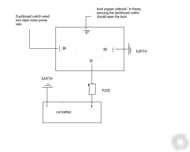
If I was just installing one push button it would be easy enough I would use the diagram below. Power from positive on rear wiper motor to a dashboard switch and to relay then to popper. Negative to relay and then to popper.
This way it only works in position 2 on the ignition.
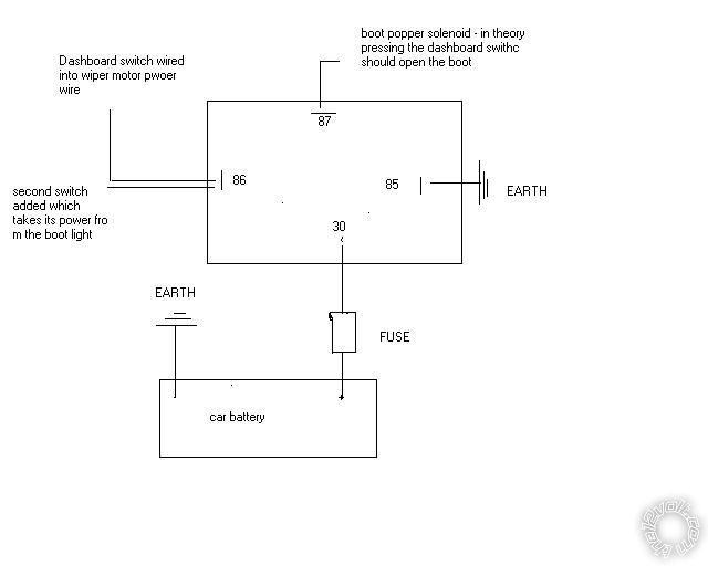
But I also want to add a second push switch can I just connect the second switch to point 86 like this
Power from positive on the boot light to switch mounted in rear wiper hole and to relay then to popper. Negative to relay and then to popper.
This works as long as the car is unlocked .
Yes the rear wiper arm has been removed. I have a smoothed tailgate that I will be putting on the car so there will be no button to open the boot. So I will be adding a bootpopper
The boot will be opened by the switch button I will mount in the dashboard but what I would also like to have is another push button switch mounted in the hole where the rear wiper used to be.
If I was just installing one push button it would be easy enough I would use the diagram below. Power from positive on rear wiper motor to a dashboard switch and to relay then to popper. Negative to relay and then to popper.
This way it only works in position 2 on the ignition.
But I also want to add a second push switch can I just connect the second switch to point 86 like this
Power from positive on the boot light to switch mounted in rear wiper hole and to relay then to popper. Negative to relay and then to popper.
This works as long as the car is unlocked .
Posted: February 16, 2010 at 3:46 PM / IP Logged
 Printable version
| You cannot post new topics in this forum You cannot reply to topics in this forum You cannot delete your posts in this forum You cannot edit your posts in this forum You cannot create polls in this forum You cannot vote in polls in this forum |

| Search the12volt.com |
Follow the12volt.com 
Thursday, May 23, 2024 • Copyright © 1999-2024 the12volt.com, All Rights Reserved • Privacy Policy & Use of Cookies

Thursday, May 23, 2024 • Copyright © 1999-2024 the12volt.com, All Rights Reserved • Privacy Policy & Use of Cookies
Disclaimer:
*All information on this site ( the12volt.com ) is provided "as is" without any warranty of any kind, either expressed or implied, including but not limited to fitness for a particular use. Any user assumes the entire risk as to the accuracy and use of this information. Please
verify all wire colors and diagrams before applying any information.
