the12volt.com spacer
icon

project ?


Post ReplyPost New Topic
< Prev Topic Next Topic >
goinpro 
Member - Posts: 6
Member spacespace
Joined: September 06, 2005
Posted: September 06, 2005 at 10:52 PM / IP Logged  

I want to use one of these for my switches

http://fbimini.com/assets/files/product_images/250497.jpg

but seeing as they are all momentary switches is there a way that i could use them to a relay and then keep the acc. on then hit the switch again to turn it off?

hotwaterwizard 
Silver - Posts: 1,350
Silver spacespace
Joined: December 11, 2003
Location: California, United States
Posted: September 07, 2005 at 12:22 AM / IP Logged  


project ? -- posted image.

Look at this!

Here are More!

http://www.redshydros.com/id35.htm

project ? -- posted image.

http://207.97.200.166/index.asp?PageAction=VIEWPROD&ProdID=471

project ? -- posted image.

http://fbimini.com/product.asp?actiontype=flicks&idno=3886

project ? -- posted image.

John DeRosa (Hotwaterwizard)
Stockton California
When in doubt, try it out !
KPierson 
Platinum - Posts: 3,527
Platinum spaceThis member consistently provides reliable informationspace
Joined: April 14, 2005
Location: Ohio, United States
Posted: September 24, 2005 at 4:47 PM / IP Logged  

You can turn any momentary swtich in to a toggle switch by using a D series Flip Flop IC chip.  You will have to create a debounce interface using an AND gate, but it will work perfectly.  Do a google search for "D Flip Flop toggle circuit" and you can find some easy schematics to follow.

You can also set it up with three relays I believe to turn a momentary switch to a toggle switch.

Your final option is to use a microcontroller.  You could eliminate all the external parts of the D series flip flow, including the debounce circuit, and be left with just an 8 pin IC chip and a voltage regulator.  If you are at all interested in this setup let me know, I can give you more information.

Kevin Pierson
hotwaterwizard 
Silver - Posts: 1,350
Silver spacespace
Joined: December 11, 2003
Location: California, United States
Posted: September 25, 2005 at 4:16 PM / IP Logged  

Why get so complicated just buy new switches.

Switches are cheep and you will have way less problems.

Flipflops, AND Circuits, Debounce Circuits, Buffers, power supplies, circuit boards, not to mention current handling capibilities., ECT ECT ECT

John DeRosa (Hotwaterwizard)
Stockton California
When in doubt, try it out !
KPierson 
Platinum - Posts: 3,527
Platinum spaceThis member consistently provides reliable informationspace
Joined: April 14, 2005
Location: Ohio, United States
Posted: September 27, 2005 at 4:05 AM / IP Logged  
hotwaterwizard wrote:

Why get so complicated just buy new switches.

Switches are cheep and you will have way less problems.

Flipflops, AND Circuits, Debounce Circuits, Buffers, power supplies, circuit boards, not to mention current handling capibilities., ECT ECT ECT

It's really not that complicated.  Digital electronics are a MUCH better way to go then relay logic (check out industrial controls, for example).  You can buy expensive latching relays and what not, or for $3 you can build a circuit that will work better in most cases then relays.  The internet has made it possible for electronically experianced people (ie installers) who know nothing or very little about electronic circuits to reserach, design, and build simple circuits.  With the low costs of the project you could build 5 and it wouldn't cost much.

Also, I for one, prefer momentary switches to toggle switchs for style and function.  I would take a well made push button switch over a toggle switch any day of the week, espcially considering how easy it is to convert them to toggle switches!

Kevin Pierson
hotwaterwizard 
Silver - Posts: 1,350
Silver spacespace
Joined: December 11, 2003
Location: California, United States
Posted: September 28, 2005 at 10:27 PM / IP Logged  

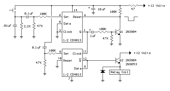
I have Installed and Repaired Stereos for years. Most need atleast 10 amps to operate. Show me a schematic diagram of one of your nifty Flipflop Circuits that will handle 10 amps continuous current that is not complicated.

Here is one I have

project ? -- posted image.

John DeRosa (Hotwaterwizard)
Stockton California
When in doubt, try it out !
KPierson 
Platinum - Posts: 3,527
Platinum spaceThis member consistently provides reliable informationspace
Joined: April 14, 2005
Location: Ohio, United States
Posted: October 06, 2005 at 12:19 AM / IP Logged  
You're name wouldn't happen to be Bill Bowden, would it? I only ask because I stubled across this page: http://ourworld.compuserve.com/homepages/Bill_Bowden/page9.htm. This guy has 'your' circuit posted there and claims the credit for it.
Any digital IC chip is going to need a dedicated driver circuit (transistor). The D series flip flop will use the same transistor output as 'your' JK flip flops in the circuit you posted.
My circuit below does not have a debounce component, because I don't have the time to add it. You could do it several different ways, but the easiest would be an RC setup and a buffer.
If it were me doing it, I would use an Atmel Tiny11 microcontroller. They cost $0.50. They only downside is that they operate on 5vdc, so a voltage regulator and a few caps will be necesarry. But, they have built in pull up resistors and you can software program the debounce. You will still need the transistor output.
Here is the D flip flop circuit that requires no code or programming. Please note that this is a 'simple' bare bones circuit. If I were building it I would include a few more resistors to control the current flow in the base of the transistor and out of the collector of the transistor.
project ? -- posted image.
Kevin Pierson
KPierson 
Platinum - Posts: 3,527
Platinum spaceThis member consistently provides reliable informationspace
Joined: April 14, 2005
Location: Ohio, United States
Posted: October 06, 2005 at 12:23 AM / IP Logged  
project ? -- posted image.
Kevin Pierson

Sorry, you can NOT post a reply.
This topic is closed.

  Printable version Printable version Post ReplyPost New Topic
You cannot post new topics in this forum
You cannot reply to topics in this forum
You cannot delete your posts in this forum
You cannot edit your posts in this forum
You cannot create polls in this forum
You cannot vote in polls in this forum

  •  
Search the12volt.com
Follow the12volt.com Follow the12volt.com on Facebook
Wednesday, June 5, 2024 • Copyright © 1999-2024 the12volt.com, All Rights Reserved Privacy Policy & Use of Cookies
Disclaimer: *All information on this site ( the12volt.com ) is provided "as is" without any warranty of any kind, either expressed or implied, including but not limited to fitness for a particular use. Any user assumes the entire risk as to the accuracy and use of this information. Please verify all wire colors and diagrams before applying any information.

Secured by Sectigo
the12volt.com spacer
Support the12volt.com
Top
the12volt.com spacer